
Continuous extraction system for herbicide production

A herbicide and extraction technology, applied in the field of continuous extraction systems for herbicide production, can solve the problems of low extraction efficiency, inability to achieve continuous extraction, excessive time and labor consumption, etc., and achieve thorough, cleaner, and thorough extraction. , the effect of increasing the contact area

Inactive Publication Date: 2021-07-13
安徽省圣丹生物化工有限公司
View PDF8 Cites 0 Cited by
  • Summary
  • Abstract
  • Description
  • Claims
  • Application Information

AI Technical Summary

Problems solved by technology

[0003] The purpose of the present invention is to provide a continuous extraction system for herbicide production, to solve the problem that the extraction equipment proposed in the above background technology cannot achieve continuous extraction, and the extraction alone will consume too much time and manpower, resulting in low extraction efficiency question

Method used


Image

  • Continuous extraction system for herbicide production
  • Continuous extraction system for herbicide production
  • Continuous extraction system for herbicide production

Examples


specific Embodiment approach 1

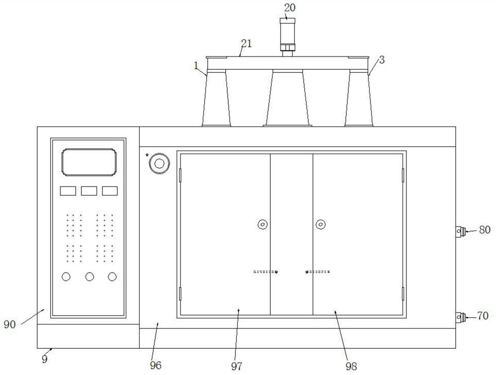
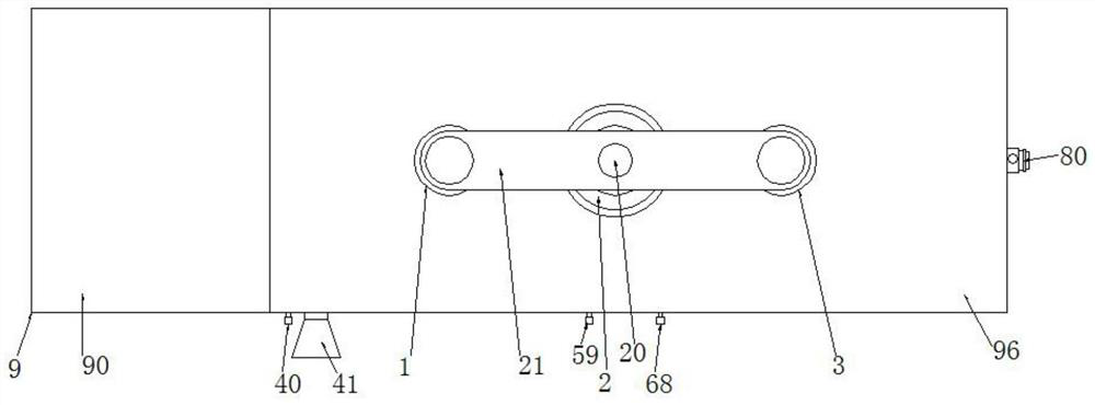
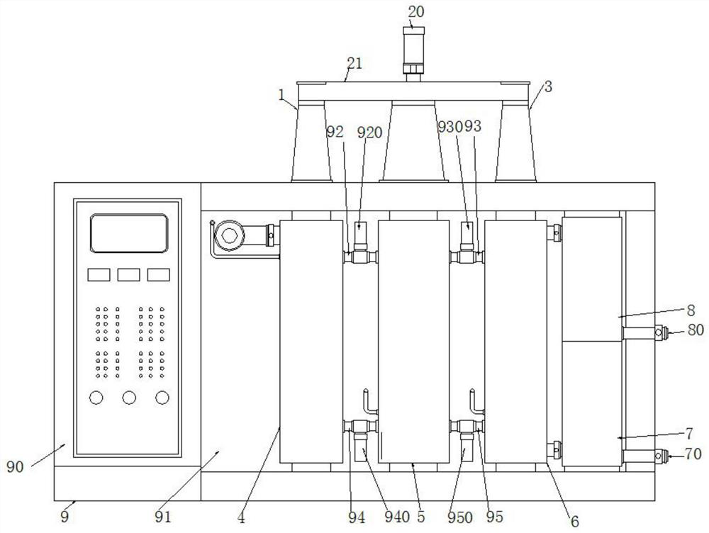
[0029] Specific implementation mode one, refer to Figure 1-9 , the present invention provides a technical solution: a continuous extraction system for herbicide production, comprising a first extraction tank structure 4, a second extraction tank structure 5, a third extraction tank structure 6 and a body 9, the left side of the body 9 The control cabinet 90 is arranged on the upper part, and the right part of the body 9 is provided with an extraction cabinet 96, and an installation cavity 91 is opened in the extraction cabinet 96, and the first extraction tank structure 4 is installed in the left part of the installation cavity 91, and the installation cavity The second extraction tank structure 5 is installed in the middle part of 91, and the third extraction tank structure 6 is installed in the right part of the installation cavity 91, and the light liquid collection tube 8 is installed on the upper right side of the third extraction tank structure 6, and the light liquid T...

specific Embodiment approach 2

[0031] Specific embodiment 2. This embodiment is a further limitation of specific embodiment 1. In the present invention, the setting of the first protective cover 1 is used to protect the first rotating shaft 10, and the first rotating shaft 10 and the first extraction tank structure 4 in the first A stirring shaft 46 is connected together, so that the first stirring shaft 46 is driven to rotate together while the first rotating shaft 10 is rotating, so as to quickly stir the mixed liquid and the extracting liquid in the first extraction tank structure 4, so that they are evenly mixed together, It is helpful for rapid extraction and separation of the mixed liquid initially.

specific Embodiment approach 3

[0032] Specific embodiment 3, this embodiment is a further limitation of specific embodiment 1, the setting of the second protective cover 2 in the present invention is used to protect the second rotating shaft 22, the second rotating shaft 22 and the first extraction tank structure 5 in the second The two stirring shafts 51 are connected together, so that the second stirring shaft 51 is driven to rotate together while the second rotating shaft 22 is rotating, so as to quickly stir the mixed liquid and the extracting liquid in the second extraction tank structure 5 to make them evenly mixed together, It is helpful for rapid extraction and separation of the mixed solution for the second time.


PUM


Abstract

A continuous extraction system for herbicide production, disclosed in the invention, comprises a first extraction tank structure, a second extraction tank structure, a third extraction tank structure and a machine body, the first extraction tank structure is installed at the left part in a mounting cavity, the second extraction tank structure is installed at the middle part in the mounting cavity, and the third extraction tank structure is installed at the right part in the mounting cavity; and a light liquid collecting cylinder is mounted above the right side of the third extraction tank structure, and a heavy liquid collecting cylinder is mounted below the right side of the third extraction tank structure. According to the continuous extraction system for herbicide production, a rotating shaft is used for rapidly rotating a stirring shaft, so that shearing force generated by a mixed liquid and an extraction agent in the tank enables the mixed liquid to be broken into a plurality of fine liquid drops, strong vortex motion is generated in the mixed liquid, meanwhile, the contact area of the extraction agent and a stock solution is increased, and the split fine liquid drops are extracted in the tank, therefore, the mixed liquid can be continuously extracted for multiple times, the purpose of continuous extraction is achieved, and the extraction is more thorough and cleaner.

Description

technical field [0001] The invention relates to the related technical field of herbicide production, in particular to a continuous extraction system for herbicide production. Background technique [0002] In the herbicide production process, extraction equipment will be used, and extraction equipment is a type of mass transfer equipment used for extraction operations, which can achieve perfect separation of components contained in the feed liquid. Extraction equipment can be divided into mixing and clarification according to the structure. However, the extraction equipment currently popular in the market has a fast phase separation speed, but its mixing time is usually only a few seconds or tens of seconds, which is only suitable for certain materials with fast extraction kinetics , not suitable for materials with slow kinetics, and continuous extraction cannot be achieved. This extraction method has the defects of low extraction efficiency and long extraction time. Conten...

Claims


Application Information

Patent Timeline
Patent Type & Authority Applications(China)
IPC IPC(8): B01D11/04
CPCB01D11/04B01D11/0488
Inventor 方向明钱同兰范泽求范进林
Owner 安徽省圣丹生物化工有限公司
Learn More