
Spiral pipe gap machining equipment

A technology for processing equipment and spiral tubes, which is applied in the field of spiral tube processing equipment, can solve problems such as corrugated tube surface damage and complex molding process, and achieve high production efficiency, simple operation, and large-scale modern production.

Pending Publication Date: 2021-07-13
浙江臻龙能源设备科技有限公司
View PDF0 Cites 0 Cited by
  • Summary
  • Abstract
  • Description
  • Claims
  • Application Information

AI Technical Summary

Problems solved by technology

[0003] The purpose of the present invention is to provide a spiral tube gap processing equipment for the defects of the above-mentioned prior art that the forming process is complex and easily damage the surface of the bellows, which can achieve the purpose of simplifying the forming process and not causing damage to the surface of the bellows

Method used


Image

  • Spiral pipe gap machining equipment
  • Spiral pipe gap machining equipment
  • Spiral pipe gap machining equipment

Examples


Embodiment Construction

[0034] The present invention will be further described below in conjunction with the accompanying drawings and specific examples, but is not limited to the present invention.

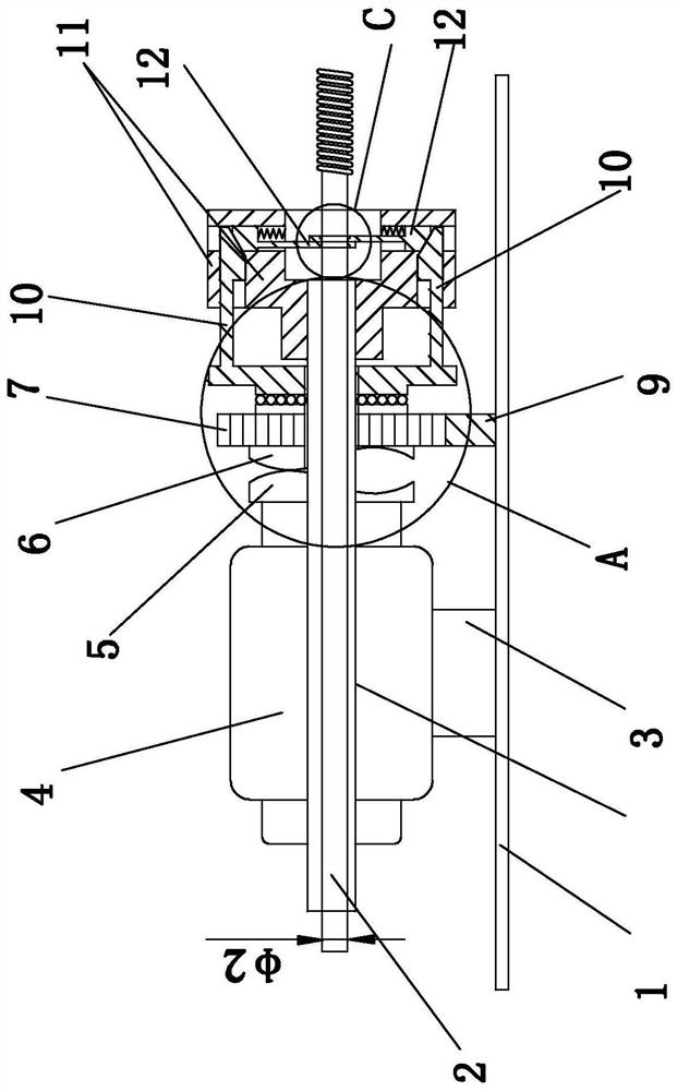
[0035] Such as Figure 1 to 9 As shown, a spiral tube gap processing apparatus, the spiral tube 18 formed by the processing is used in conjunction with the new cooker tube, such as figure 1 As shown, including the base 1 and the processed steel pipe 2, the outer diameter φ1 of the processed steel pipe 2 is 12.7 mm;

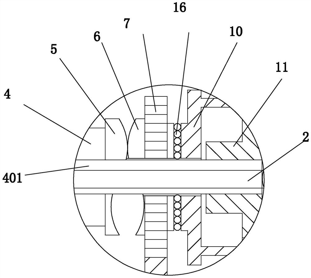
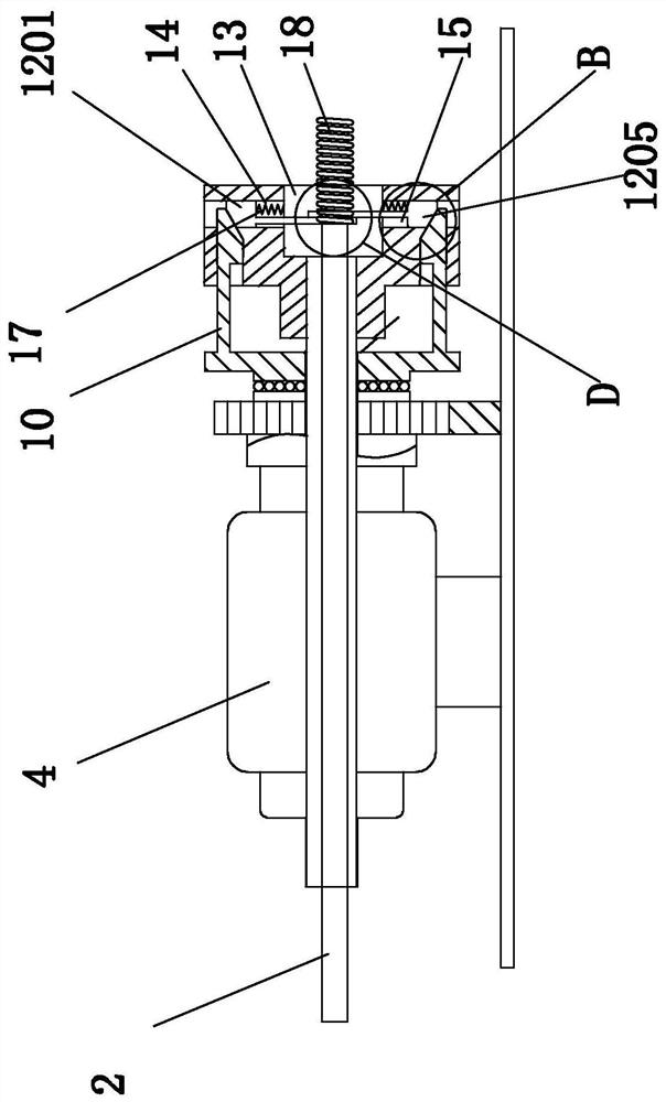
[0036] Such as figure 1 The motor holder 3, the servo motor 4, the cam A 5, the cam B 6, the gear 7, the rack 8, the cylinder 9, the translation block 10, the outer casing 11 and the molding die 12; the cam A 5 left end and servo The motor 4 is fixed to the right end, and the cam A 5 cannot be rotated; the flat block 10 includes a flat block 10 and a flat block 10, and the molded mold 12 includes a molded mold A1201 and a molding mold B 1205; the motor bracket 3 fixed setting On the left side of...


PUM


Abstract

The invention discloses spiral pipe gap machining equipment, and belongs to the technical field of spiral pipe machining. The equipment comprises a motor support, a servo motor, a cam A, a cam B, a gear, a rack, an air cylinder, a translation block, a shell and a forming mold. The translation block comprises an upper translation block and a lower translation block, and the forming mold comprises a forming mold A and a forming mold B. A transmission shaft cam A, a cam B, a gear, a translation block and a shell of the servo motor are all provided with central through holes, and a transmission shaft mounting hole and central through holes of the cam A, the cam B, the gear, the translation block, the shell and the forming mold are sequentially arranged on a transmission shaft of the servo motor in a sleeving manner from left to right. Inclined planes A are arranged on the inner side surfaces of the right front ends of the upper translation block and the lower translation block. The forming mold A comprises a sliding block, a mold hole A and a mold rod, and the forming mold B comprises a sliding block, a mold hole B and a mold rod. The left outer side surface of the sliding block is an inclined plane B which is matched with the inclined planes A. The equipment has the advantages of automatic production, simple operation and high production efficiency.

Description

Technical field [0001] The present invention is a spiral tube processing apparatus, and more particularly to a processing apparatus for direct processing of a spiral tube gap using a steel pipe, which belongs to a spiral tube processing technology. Background technique [0002] This product is used in conjunction with the new cooker tube, and is applied to the subsequent cooker tube forming assembly integrated molding process. Now the integrated molding process of the cooker is complex, unreasonable, is inconvenient to use; the position of the production of spiral sections and straight pipe sections is uncontrollable, the straight pipe section needs to be made as a spiral section, and then stretch and roller is a straight pipe section, and the surface of the bellows is easy. Resulting damage. Inventive content [0003] It is an object of the present invention to be in the above-described prior art, a deficiencies that cause damage to the surface of the bellows, which provide a s...

Claims


Application Information

Patent Timeline
Patent Type & Authority Applications(China)
IPC IPC(8): B21D15/06
CPCB21D15/06
Inventor 谷建伟
Owner 浙江臻龙能源设备科技有限公司
Learn More