
High-low voltage power cabinet grooving machining equipment

A power cabinet and groove processing technology, applied in the field of power cabinets, can solve the problems of cabinet door position deviation, affecting slotting efficiency, and consuming too much time, so as to achieve the effect of improving work efficiency, improving efficiency, and reducing time consumption

Inactive Publication Date: 2021-07-13
安徽启诚电气科技有限公司
View PDF9 Cites 0 Cited by
  • Summary
  • Abstract
  • Description
  • Claims
  • Application Information

AI Technical Summary

Problems solved by technology

[0003] The traditional slotting method is usually punching and slotting, but the slotting method is usually single-slot punching, which is less efficient, and because the positioning of the cabinet door requires multi-directional fixtures for positioning, each set of fixtures requires a certain amount of time. After the fixture is fully positioned, it will take a lot of time, which will affect the slotting efficiency. After the fixture is positioned, the cabinet door may still have a small position deviation under the action of a large punching force during the slotting process. Due to the situation of shifting, the position of the actual slotting position and the scheduled slotting position deviate

Method used


Image

  • High-low voltage power cabinet grooving machining equipment
  • High-low voltage power cabinet grooving machining equipment
  • High-low voltage power cabinet grooving machining equipment

Examples


Embodiment Construction

[0034] Embodiments of the present invention will be described below with reference to the drawings. In the process, in order to ensure the clarity and convenience of illustration, we may exaggerate the width of the lines or the size of the constituent elements in the diagram.

[0035] In addition, the following terms are defined based on the functions in the present invention, and may be different according to the user's or operator's intention or practice. Therefore, these terms are defined based on the entire content of this specification.

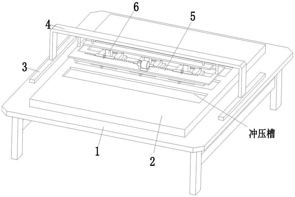
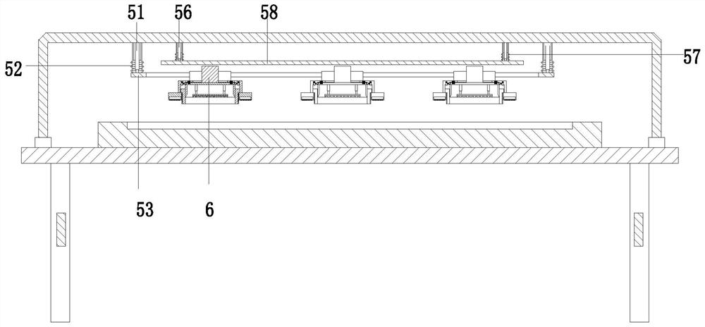
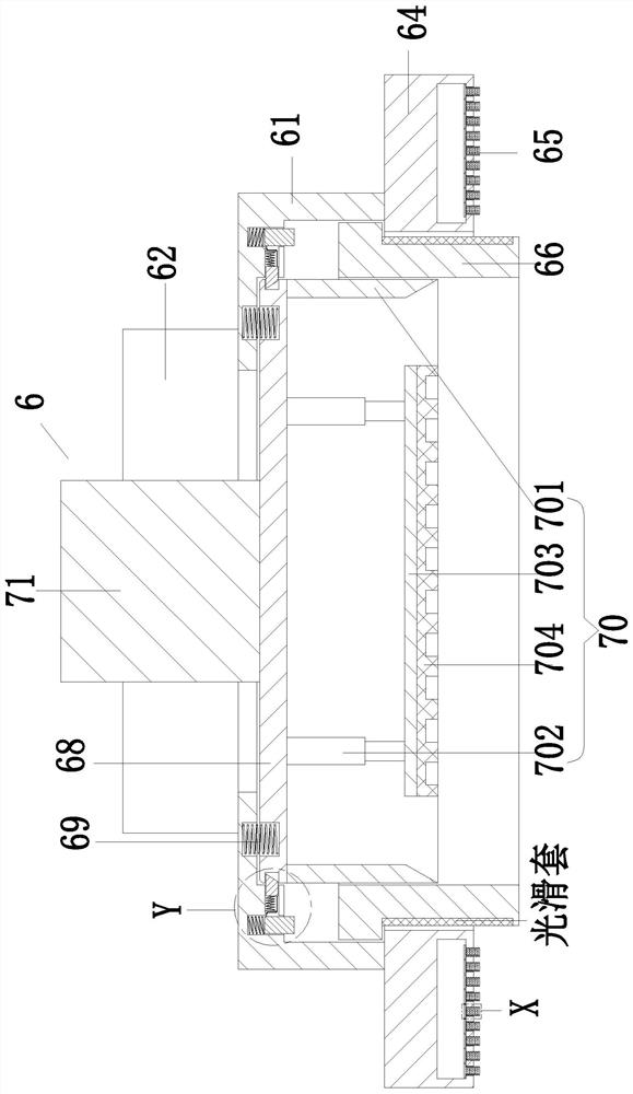
[0036] Such as Figure 1 to Figure 11 As shown, a high and low voltage power cabinet slotting processing equipment includes a processing bed 1, a positioning block 2, an electric slider 3, a U-shaped frame 4, an adjustment device 5, and a slotting device 6. The middle part of the processing bed 1 A positioning block 2 is installed, and electric sliders 3 are installed on the left and right ends of the processing bed 1. A U-shaped frame...


PUM


Abstract

The invention relates to high-low voltage power cabinet grooving machining equipment. The high-low voltage power cabinet grooving machining equipment comprises a machining bed, a positioning block, electric sliding blocks, a U-shaped frame, an adjusting device and grooving devices, the positioning block is installed in the middle of the machining bed, the electric sliding blocks are installed at the left end and the right end of the machining bed, the U-shaped frame is arranged between the electric sliding blocks, the adjusting device is installed at the upper end of the U-shaped frame, and the grooving devices are uniformly mounted on the adjusting device. The problems that a traditional grooving mode is generally single-groove punching forming, the efficiency is low, due to the fact that multi-directional clamps are needed for positioning when a cabinet door is positioned, positioning of each set of clamps needs a certain time, and after the clamps are completely positioned, much time is consumed, the grooving efficiency is affected, and after the clamps are positioned, in the grooving process, under the action of large stamping force, the cabinet door can still have the situation of small-amplitude position deviation, and the situation that the actual grooving position and the preset grooving position have position deviation is caused.

Description

technical field [0001] The invention relates to the related technical field of power cabinets, in particular to a slotting processing equipment for high and low voltage power cabinets. Background technique [0002] The power cabinet refers to the combination of electrical control cabinets that provide power for the normal operation of the entire machine, including contactors, frequency converters, high-voltage cabinets, transformers, etc. Its function is to supply power to electrical equipment, start and stop operating electrical equipment, To detect the operation of the equipment, the high and low voltage power cabinet is a kind of power cabinet. The high and low voltage power cabinet is usually assembled from the cabinet body and the cabinet door. During the processing of the cabinet door, the surface needs to be grooved. After being put in, the display screen can be aligned with the opened slot, so that the staff can check the data in time. [0003] The traditional slott...

Claims


Application Information

Patent Timeline
Patent Type & Authority Applications(China)
IPC IPC(8): B21D17/02B21D43/00
CPCB21D17/02B21D43/003
Inventor 程道伟
Owner 安徽启诚电气科技有限公司
Learn More