
Quality detection device for LED production

A detection device and quality technology, applied in the field of quality detection devices for LED production, can solve problems such as low detection rate and complicated operation, and achieve the effect of preventing breakage

Active Publication Date: 2021-07-13
福建晶谱瑞照明科技有限公司
View PDF6 Cites 2 Cited by
  • Summary
  • Abstract
  • Description
  • Claims
  • Application Information

AI Technical Summary

Problems solved by technology

[0004] In order to overcome the shortcomings of complex operation and low detection rate, the technical problem of the present invention is to provide an automatic operation process, reduce labor costs, and improve the quality detection device for LED production.

Method used


Image

  • Quality detection device for LED production
  • Quality detection device for LED production
  • Quality detection device for LED production

Examples


Embodiment 1

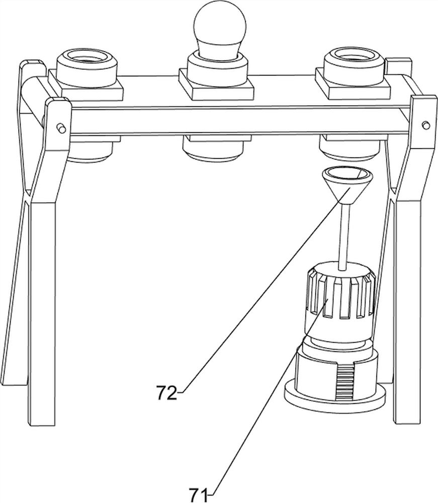
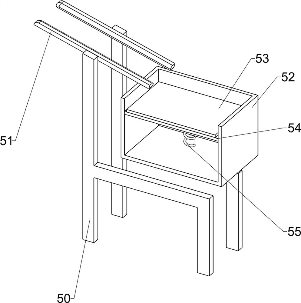
[0065] A quality inspection device for LED production, such as figure 1 As shown, it includes a base 1, a lifting mechanism 2 and a detection mechanism 3. The lifting mechanism 2 is connected to the front and rear sides of the upper part of the base 1, and the detection mechanism 3 is connected to the front and rear sides of the upper part of the base 1.

[0066] When the device needs to be used, the user can lift the light bulb between the lifting mechanism 2, start the lifting mechanism 2, the telescopic rod of the lifting mechanism 2 is extended, and drives the lifting mechanism 2 to move inward and upward, so as to provide The driving force is to facilitate the follow-up operation. When the lifting mechanism 2 moves up to contact with the detection mechanism 3, it pushes the detection mechanism 3 to move to the left. At this time, the detection mechanism 3 is compressed to detect the bulb, so as to achieve automatic detection of the bulb For the purpose of good or bad qual...

Embodiment 2

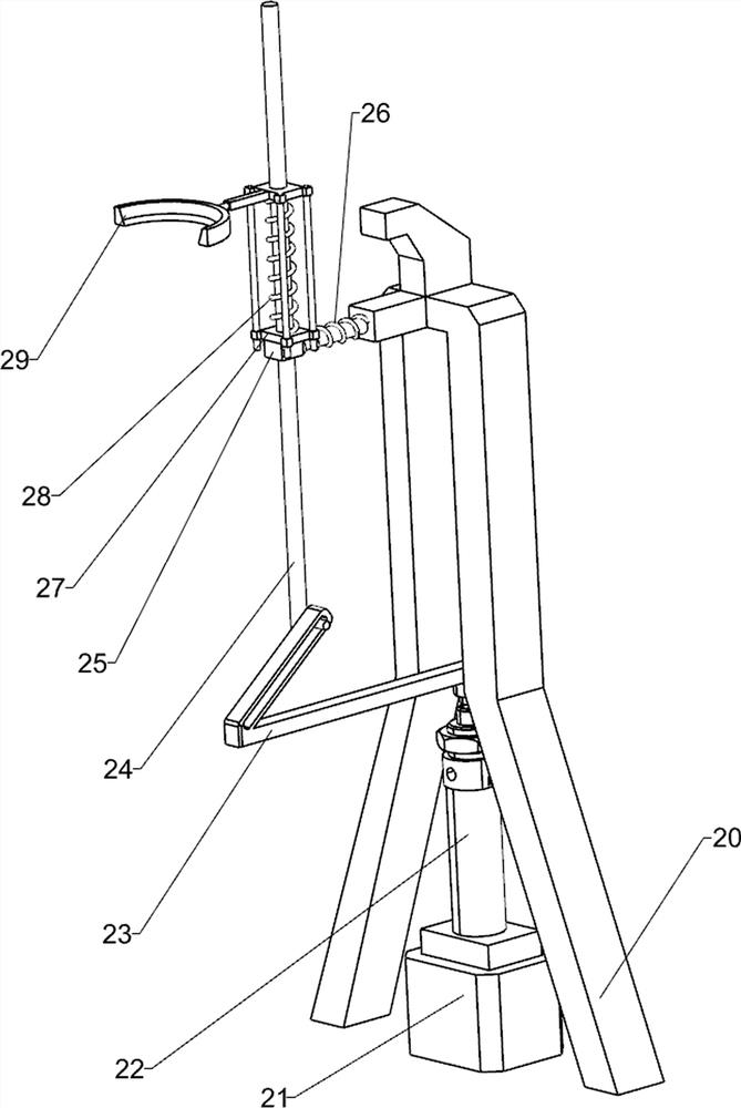
[0068] On the basis of Example 1, such as figure 2As shown, the lifting mechanism 2 includes a first support frame 20, a fixed seat 21, a cylinder 22, a push rod 23, a first spring 26, a sliding rod 24, a block 27, a sliding shaft 25, a second spring 28 and a block 29 , both sides of the upper part of the base 1 are connected with a first support frame 20, both sides of the upper part of the base 1 are connected with a fixed seat 21, the fixed seat 21 is connected with a cylinder 22, and the top of the output shaft of the cylinder 22 is connected with a Push rod 23, on the first support frame 20, all slide shafts 25 are slidably connected, and slide rods 24 are all slidably connected in the slide shafts 25, and slide rods 24 are slidably connected with push rods 23. A first spring 26 is wound around, and a block 27 is connected to the sliding rod 24, and a block 29 is slidably connected in the block 27, and the block 29 is slidably connected to the sliding rod 24, and the sec...


PUM


Abstract

The invention relates to a quality detection device, in particular to a quality detection device for LED production. The invention aims to provide a quality detection device for LED production, by the quality detection device for LED production, an automatic operation process is achieved, the labor cost is reduced, and the detection rate is improved. According to the technical scheme, the quality detection device for LED production comprises lifting mechanisms and detection mechanisms, wherein the lifting mechanisms are connected to both sides of the top of a base; and the detection mechanisms are connected to both sides of the top of the base. According to the quality detection device for LED production, through the cooperation of an air cylinder, a sliding rod, a stop block and a clamping block, the purposes of providing driving force for the device and facilitating subsequent operation are achieved.

Description

technical field [0001] The invention relates to a quality detection device, in particular to a quality detection device for LED production. Background technique [0002] LED lighting is light-emitting diode lighting, which is a semiconductor solid-state light-emitting device. It uses a solid semiconductor chip as a light-emitting material. In the semiconductor, the excess energy is released through the recombination of carriers to cause photon emission, and directly emits red, yellow, blue, and green light. On this basis, using the principle of three primary colors, Adding fluorescent powder can emit light of any color. The lighting fixtures manufactured using LEDs as light sources are LED lamps. Among LED lighting fixtures, LED lighting fixtures for reflection can be fully competent for any occasion, and large-area indoor lighting is not yet mature. [0003] The present invention aims at the quality inspection process of LED light bulbs produced, and develops an automatic...

Claims


Application Information

Patent Timeline
Patent Type & Authority Applications(China)
IPC IPC(8): B65G49/05B65G45/10G01R31/44
CPCB65G49/05B65G45/10G01R31/44
Inventor 钟瑾
Owner 福建晶谱瑞照明科技有限公司
Learn More