Motion detection method based on pulse array
A technology of motion detection and pulse, which is applied in the field of motion detection based on pulse array, can solve the problems of not taking advantage of the advantages of time and space of pulse sequence
- Summary
- Abstract
- Description
- Claims
- Application Information
AI Technical Summary
Problems solved by technology
Method used
Image

Examples
Embodiment 1
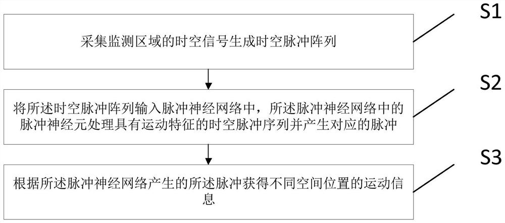
[0036] This application provides a motion detection method based on pulse array, such as figure 1 As shown, the application provides a motion detection method based on a pulse array, comprising the following steps:
[0037] Collect spatio-temporal signals in the monitoring area to generate spatio-temporal pulse arrays;
[0038] The spatiotemporal pulse array is input into the spiking neural network, and the spiking neurons in the spiking neural network process the spatiotemporal pulse sequence with motion characteristics and generate corresponding pulses;
[0039] The motion information of different spatial positions is obtained according to the pulses generated by the spiking neural network.
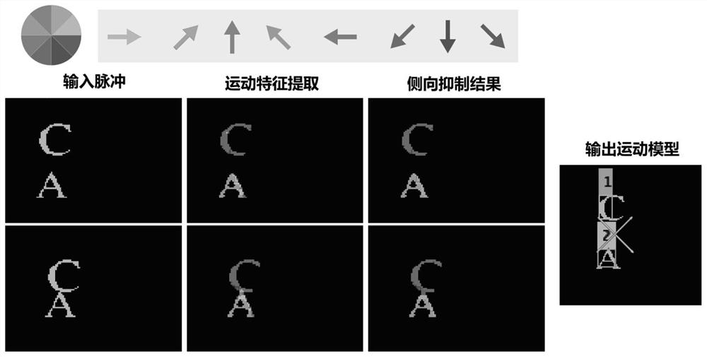
[0040] The impulse neural network includes a feature extraction layer and a motion detection layer. The feature extraction layer detects motion patterns and obtains pulse sequences corresponding to different motion features. The motion detection layer detects motion models according to...
Embodiment 2
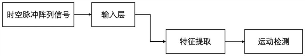
[0059] This application provides a motion detection method based on a pulse array. First, the optical signals of each spatial position in the monitoring area are collected, and at the same time, the signals of each spatial position are accumulated to obtain the signal cumulative intensity value; once a certain space When the signal cumulative strength value of the position exceeds the preset emission threshold, a pulse signal is output; the pulse signals corresponding to each spatial position are arranged into a binary sequence according to time, and the binary sequences corresponding to all spatial positions form a pulse array. image 3 It is a flow chart of motion detection of three-dimensional spatiotemporal pulse array, such as image 3 As shown, the temporal filter processing method based on the short-term plasticity model includes the following steps:
[0060] Step 1, input a two-dimensional array formed by the pulse array at each moment into the input layer; an example ...
Embodiment 3
[0072] The pulse array-based motion detection method proposed in this application currently has another retina-like camera that can generate pulse event signals. The processing flow is as follows: Figure 4 shown. Dynamic Vision Sensor (Dynamic Vision Sensor, DVS) is a visual sensor that imitates the sensitive mechanism of retinal peripheral cells to brightness changes. It generates On events and Off events by judging whether the brightness changes exceed a certain threshold. On events indicate that the threshold changes exceed a certain positive value, and Off events The event indicates that the threshold change is lower than a certain negative value; the pulse generated by DVS is expressed in the address event form of (x, y, t, p) quadruple, (x, y) is the two-dimensional spatial position of the pulse emission, and t is The timestamp of this pulse event, p represents the event polarity (On or OFF, represented by "1" and "-1" respectively). When using the pulse event generate...
PUM
 Abstract
Description
Claims
Application Information
 - R&D
- Intellectual Property
- Life Sciences
- Materials
- Tech Scout
- Unparalleled Data Quality
- Higher Quality Content
- 60% Fewer Hallucinations
Browse by: Latest US Patents, China's latest patents, Technical Efficacy Thesaurus, Application Domain, Technology Topic, Popular Technical Reports.
© 2025 PatSnap. All rights reserved.Legal|Privacy policy|Modern Slavery Act Transparency Statement|Sitemap|About US| Contact US: help@patsnap.com