High-gain forward-flyback laminated boost converter

A boost converter, forward and flyback technology, used in high-efficiency power electronic conversion, conversion of DC power input to DC power output, instruments, etc., can solve the input current discontinuity, increase the volume of the output capacitor, and increase the conduction loss. and other problems to achieve the effect of optimizing input current, continuous input current and reducing ripple

Active Publication Date: 2021-07-13
BEIJING JIAOTONG UNIV
View PDF4 Cites 0 Cited by
  • Summary
  • Abstract
  • Description
  • Claims
  • Application Information

AI Technical Summary

Problems solved by technology

[0013] 2) The conduction time of the switch tube is long, which increases the conduction loss;
[0014] 3) The output diode conduction time is short, the current is large, and the reverse recovery time is long
[0025] 1) The input current is discontinuous;
[0026] 2) The switched capacitor current has a current peak when the switch tube is turned off, which makes the corresponding output capacitor C 3 There is a spike in the current on the circuit, which increases the volume of the output capacitor;
[0027] 3) The switching capacitor as an energy buffer circuit reduces the overall efficiency of the converter

Method used


Image

  • High-gain forward-flyback laminated boost converter
  • High-gain forward-flyback laminated boost converter
  • High-gain forward-flyback laminated boost converter

Examples


Embodiment Construction

[0055] Contraction below Figure 5 ~ 6 The present invention will be further described in further detail.

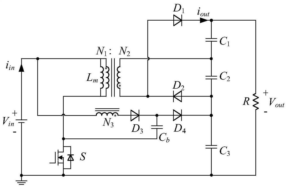
[0056] The present invention proposes a high gain positive antitock layer boost converter, a circuit diagram of a converter such as Figure 5 Indicated. The number of turns of the primary winding of the transformer is n 1 , The number of turns of the secondary winding is n 2 , The number of turns of the third winding is n 3 K 1 K 2 For the ratio of transformers, where K 1 = N 2 / N 1 K 2 = N 3 / N 1 . D is the duty cycle of the power switch tube S, the control signal and the main waveform such as Figure 6 Indicated. The converter described in this application has a continuous and high efficiency characteristics in high gain conditions.

[0057] High gain positive anti-stacked layer boost converters use stacks and leak energy ideas. The third windings and diodes are introduced using laminated ideas. To reduce the volume of the converter, the third winding is coupled to the tran...


PUM


Abstract

The invention relates to a high-gain forward-flyback laminated boost converter which comprises an input voltage source Vin, a power switch tube S, a diode D1, a diode D2, a diode D3, an output capacitor C1, an output capacitor C2, an output capacitor C3, a load R and a transformer, and is characterized in that the transformer is additionally provided with a third winding; the converter adopts the idea of lamination and energy leakage, the input voltage source is divided into two paths of input, one path of input is input to the forward-flyback converter for energy output, and the other path of input is used for energy output through the third winding. Due to the existence of the third winding, the input voltage can be connected in series with the voltage induced by the third winding in the forward direction and then connected in series with the output capacitor of the forward-flyback converter to supply power to the load, so that the converter has higher gain.

Description

Technical field [0001] The present invention relates to the field of power electronic circuit DC converters, and more particularly to a high gain positive antitocking layer boost converter, which can output the input DC low voltage to DC high pressure, and can achieve high gain Guaranteed high efficiency, input current continuous characteristics. Background technique [0002] Procedure of the prior art: [0003] Boost converters are often used for non-sub-boost converters for ordinary boost applications, such as figure 1 Indicated. Where V in Indicates the direct source input, L is inductance, S is the power switch tube, D is the diode, C is the output capacitor, and R is load. The important waveform of the BOOST converter is like figure 2 Indicated. The Boost operation mode in the continuous mode of inductive current is as follows. [0004] Modal analysis [0005] Stage one (T 0 -t 1 : The power switch pipe S is turned on, the voltage L is equal to the input voltage, according t...

Claims


Application Information

Patent Timeline
IPC IPC(8): H02M3/335H02M1/14H02M1/42
CPCH02M3/33523H02M1/14H02M1/42Y02B70/10
Inventor 李艳曹博武魏芳宜田野郭希铮杨晓峰黄先进王琛琛周明磊王剑李凯
Owner BEIJING JIAOTONG UNIV
Why Eureka
Try Eureka