A soft-switching high-gain converter with dual-input inductance and its control method

A high-gain, soft-switching technology, applied in the direction of converting DC power input to DC power output, output power conversion device, adjusting electrical variables, etc. High loss and cost problems, to achieve the effect of reducing volume and cost, high voltage gain, and low current stress

Active Publication Date: 2022-04-22
NANTONG UNIVERSITY
View PDF7 Cites 0 Cited by
  • Summary
  • Abstract
  • Description
  • Claims
  • Application Information

AI Technical Summary

Problems solved by technology

However, this topology has the following problems: (1) The input inductor current is equal to the input current, and the average current stress is large, so the inductor volume and copper consumption are large; (2) The current ripple of the input inductor is large, and a large number of parallel circuits need to be connected at the input end. Capacitors to reduce input current ripple and improve power generation efficiency and service life of renewable energy power generation units
Since high-voltage power devices have larger on-state voltage drop (or on-state resistance) and higher prices, their on-state loss and cost are higher and their efficiency is lower.
In addition, the converter also has shortcomings such as insufficient boosting capability, large number of components, and complex structure.
In addition, most current dual-input inductor-switched-capacitor high-gain converters do not achieve zero-voltage turn-on of power transistors, resulting in large switching losses and difficult to improve system conversion efficiency.

Method used


Image

  • A soft-switching high-gain converter with dual-input inductance and its control method
  • A soft-switching high-gain converter with dual-input inductance and its control method
  • A soft-switching high-gain converter with dual-input inductance and its control method

Examples


Embodiment Construction

[0045] The following will clearly and completely describe the technical solutions in the embodiments of the present application with reference to the accompanying drawings in the embodiments of the present application. Obviously, the described embodiments are only part of the embodiments of the present application, not all of them. Based on the embodiments in this application, all other embodiments obtained by persons of ordinary skill in the art without making creative efforts fall within the protection scope of the present invention.

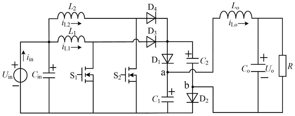
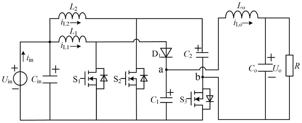
[0046] figure 2 A schematic circuit structure diagram of a soft-switching high-gain converter with dual-input inductors according to an embodiment of the present application is shown. As an exemplary and non-limiting embodiment, the converter includes an input power source U in , the first switch tube S 1 , the second switch tube S 2 , the third switch tube S 3 , the first diode D 1 , Input filter capacitor C in , the first capacitance ...


PUM


Abstract

The invention belongs to DC-DC step-up conversion technology, in particular to a double-input inductance soft-switching high-gain converter and a control method thereof, wherein the positive pole of the input power supply is connected to one end of the first inductance, one end of the second inductance, and an input filter Capacitance C in The positive pole of the input power supply is connected to the source of the first switching tube, the source of the second switching tube, the negative pole of the first capacitor, the drain of the third switching tube, and the input filter capacitor C in The drain of the first switching tube is connected to the other end of the first inductor and the anode of the first diode; the drain of the second switching tube is connected to the other end of the second inductor and the positive electrode of the second capacitor; The cathode of the first diode is connected to the positive pole of the first capacitor and one end of the output filter inductor; the negative pole of the second capacitor is connected to the source of the third switching tube, the negative pole of the output filter capacitor, and one end of the DC load; the output filter inductor The other end of the capacitor is connected to the positive pole of the output filter capacitor and the other end of the DC load.

Description

technical field [0001] The invention belongs to DC-DC step-up conversion technology, in particular to a double-input inductance soft-switching high-gain converter and a control method thereof. Background technique [0002] The terminal voltage of renewable energy generating units such as fuel cells, photovoltaic cells or batteries is low and varies widely. Therefore, the distributed renewable energy grid-connected power generation system generally adopts a two-stage structure of a DC boost converter cascaded with a voltage-type inverter. [0003] Boost converter is the most widely used DC boost converter. The input current is continuous and the structure is simple, but the actual voltage gain is affected by circuit parasitic parameters and has a maximum value (generally lower than 5), and the duty cycle corresponding to this gain is close to 1, and the current stress and voltage stress of the power tube are relatively large , the system efficiency is severely reduced. The...

Claims


Application Information

Patent Timeline
Patent Type & Authority Patents(China)
IPC IPC(8): H02M3/158
CPCH02M3/158Y02B70/10
Inventor 秦岭钱天泓许兴田民王亚芳周磊段冰莹
Owner NANTONG UNIVERSITY
Why Eureka
Try Eureka