Clock recovery circuit and method, data processing chip and electronic equipment

A clock recovery and circuit technology, applied in the field of circuits, can solve the problems of low clock signal accuracy and achieve the effect of precise clock recovery

Pending Publication Date: 2021-07-13
GALAXYCORE SHANGHAI
View PDF4 Cites 0 Cited by
  • Summary
  • Abstract
  • Description
  • Claims
  • Application Information

AI Technical Summary

Problems solved by technology

[0003] However, the accuracy of the clock signal recovered by the existing clock recovery circuit is low

Method used


Image

  • Clock recovery circuit and method, data processing chip and electronic equipment
  • Clock recovery circuit and method, data processing chip and electronic equipment

Examples


Embodiment Construction

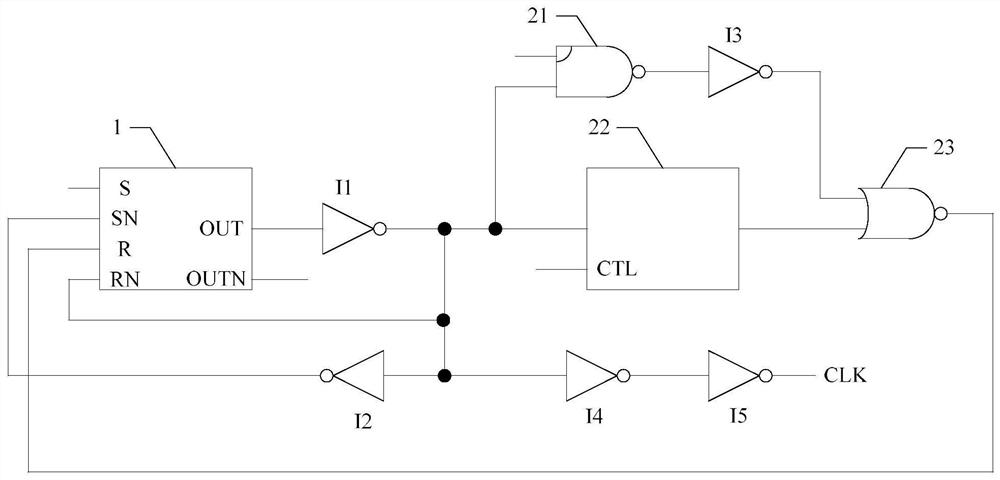
[0021] As mentioned in the background art above, the accuracy of the clock signal recovered by the existing clock recovery circuit is low.

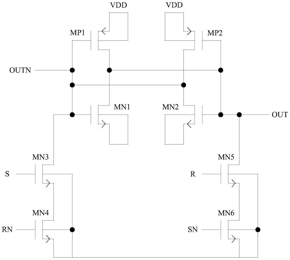
[0022] In the embodiment of the present invention, the clock recovery circuit includes a latch module, a monostable module, and an inverting logic unit, through the latch module to latch multiple groups of pulse signals input from its first set terminal, when any group of pulse signals from When it transitions from low level to high level, its rising edge is latched. The first output terminal of the inversion logic unit inverts the output signal of the first output terminal of the latch module, and the second output terminal of the inversion logic unit inverts the output signal of the first output terminal thereof. The first input terminal of the monostable module inputs the output signal of the first output terminal of the latch module through inversion, and a stable delay is obtained through the delay path of the monostable module, ther...


PUM


Abstract

The invention discloses a clock recovery circuit and method, a data processing chip and electronic equipment. The clock recovery circuit comprises a latch module, a monostable module and an anti-phase logic unit, wherein a first setting end S of the latch module inputs multiple groups of pulse signals, and when any group of pulse signals jumps from a low level to a high level, a latch rises and is output through a first output end; the input end of the anti-phase logic unit is coupled with the first output end of the latch module, the first output end of the anti-phase logic unit is coupled with the first reset end RN of the latch module, and the second output end of the anti-phase logic unit is coupled with the second set end SN of the latch module; the first input end of the monostable module is coupled with the first output end of the anti-phase logic unit , the second input end of the monostable module inputs a voltage power supply, and the output end of the monostable module is coupled with the second reset end R of the latch module; and the input signal of the first reset end RN is opposite to the input signal of the second reset end R. According to the scheme, accurate clock recovery can be realized.

Description

technical field [0001] The invention relates to the field of circuit technology, in particular to a clock recovery circuit and method, a data processing chip, and electronic equipment. Background technique [0002] The purpose of clock recovery is to track the clock drift and part of the jitter at the sending end to determine correct data sampling. A clock recovery circuit (Clock Data Recovery, CDR) is usually implemented by means of a phase locked loop (phase lock loop, PLL) circuit. [0003] However, the accuracy of the clock signal recovered by the existing clock recovery circuit is low. Contents of the invention [0004] The embodiment of the present invention solves the technical problem that the accuracy of the clock signal recovered by the clock recovery circuit is low. [0005] In order to solve the above technical problems, an embodiment of the present invention provides a clock recovery circuit, which is applied to C-PHY, including: a latch module, a monostable...

Claims


Application Information

Patent Timeline
Patent Type & Authority Applications(China)
IPC IPC(8): H03K17/22
CPCH03K17/22
Inventor 黄泽许迪
Owner GALAXYCORE SHANGHAI
Why Eureka
Try Eureka