
Electronic part automatic machining equipment

A technology of electronic parts and processing equipment, which is applied in the field of automatic processing equipment for electronic parts, can solve the problems of inability to meet the mass production of parts, low production efficiency, and high labor intensity, and achieve automatic processing, low cost, and labor low intensity effect

Inactive Publication Date: 2021-07-16
广州市新涵自动化科技有限公司
View PDF0 Cites 0 Cited by
  • Summary
  • Abstract
  • Description
  • Claims
  • Application Information

AI Technical Summary

Problems solved by technology

[0003] In the production process of electronic products, it is usually necessary to process each electronic component first, and then assemble multiple electronic components together. Some electronic components need to be drilled during the processing process. The existing The processing of electronic parts usually needs to be manually fixed, and then drilled by electric drills, which is labor-intensive, cumbersome to operate, and the production efficiency is low, which cannot meet the mass production of parts. Therefore, we propose a Automatic processing equipment for electronic components

Method used


Image

  • Electronic part automatic machining equipment
  • Electronic part automatic machining equipment
  • Electronic part automatic machining equipment

Examples


Embodiment 1

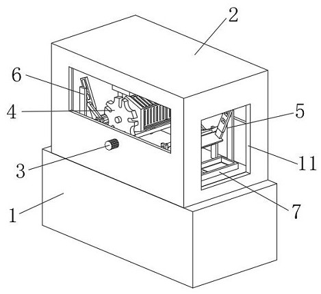
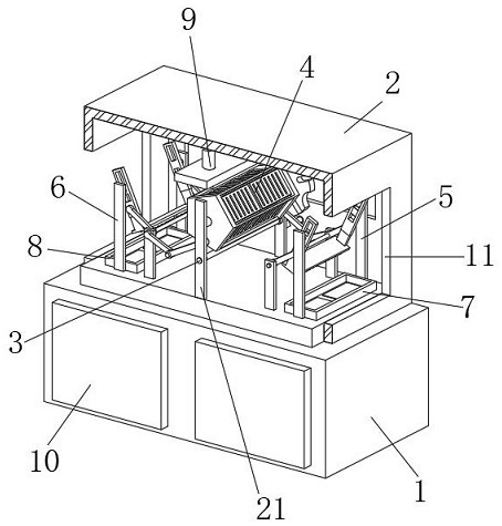
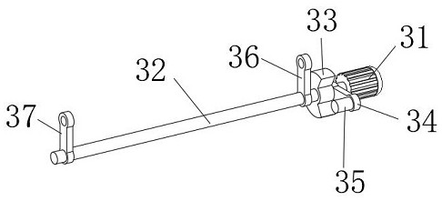
[0036] An electronic component automatic processing equipment, such as Figure 1-2 As shown, including the console 1, the upper end of the console 1 is fixedly equipped with a protective cover 2, and the front and rear sides of the middle part of the upper end of the console 1 are fixedly welded with support plates 21, and the two support plates 21 are located in the protective cover 2. The middle part of the rear end of the cover 2 is interspersed with a drive mechanism 3, and the drive mechanism 3 is movably connected with the support plate 21 through a bearing, and a positioning mechanism 4 is movably connected between the two support plates 21, and the positioning mechanism 4 is located above the drive mechanism 3 and It is connected with the drive mechanism 3 through transmission, and the left and right sides of the upper end of the console 1 are fixedly installed with a discharging mechanism 6 and a retrieving mechanism 5 respectively, and both the retrieving mechanism 5 an...

Embodiment 2

[0039] On the basis of Example 1, as Figure 6-8 As shown, an automatic processing equipment for electronic components includes an operation table 1, a protective cover 2 is fixedly installed on the upper end of the operation table 1, and support plates 21 are fixedly welded on the front and rear sides of the upper middle of the operation table 1, and the two support plates 21 are all located in the protective cover 2, the middle part of the rear end of the protective cover 2 is interspersed with a driving mechanism 3, and the driving mechanism 3 is movably connected with the support plate 21 through the bearing, and a positioning mechanism 4 is movably connected between the two support plates 21 to position The mechanism 4 is located above the driving mechanism 3 and is connected with the driving mechanism 3. The left and right sides of the upper end of the console 1 are respectively fixedly equipped with a discharging mechanism 6 and a retrieving mechanism 5, and the retrievi...

Embodiment 3

[0042] On the basis of Example 1, as Figure 3-5 As shown, an automatic processing equipment for electronic components includes an operation table 1, a protective cover 2 is fixedly installed on the upper end of the operation table 1, and support plates 21 are fixedly welded on the front and rear sides of the upper middle of the operation table 1, and the two support plates 21 are all located in the protective cover 2, the middle part of the rear end of the protective cover 2 is interspersed with a driving mechanism 3, and the driving mechanism 3 is movably connected with the support plate 21 through the bearing, and a positioning mechanism 4 is movably connected between the two support plates 21 to position The mechanism 4 is located above the driving mechanism 3 and is connected with the driving mechanism 3. The left and right sides of the upper end of the console 1 are respectively fixedly equipped with a discharging mechanism 6 and a retrieving mechanism 5, and the retrievi...


PUM


Abstract

The invention discloses electronic part automatic machining equipment, which comprises an operation table; a protective cover is fixedly installed at the upper end of the operation table; supporting plates are fixedly welded to the front side and the rear side of the middle of the upper end of the operation table; a driving mechanism is connected to the middle of the rear end of the protective cover in a penetrating and inserting mode; a positioning mechanism is movably connected between the two supporting plates; the positioning mechanism is located above the driving mechanism and is in transmission connection with the driving mechanism; the left side and the right side of the upper end of the operation table are fixedly provided with a material placing mechanism and a material taking mechanism correspondingly, and the material taking mechanism and the material placing mechanism are both in transmission connection with the driving mechanism; a No.2 material receiving tray and a No.1 material receiving tray are detachably mounted on the left side and the right side of the upper end of the operation table respectively; and a drilling machine is arranged in the middle of the upper inner wall of the protective cover. According to the electronic part automatic machining equipment provided by the invention, the structure is compact, transmission is stable, cost is low, automatic machining of parts can be achieved, the labor intensity is low, and the electronic part automatic machining equipment can be widely popularized and used in the processing process of electronic parts.

Description

technical field [0001] The invention relates to the technical field of electronic parts processing, in particular to an automatic processing equipment for electronic parts. Background technique [0002] Electronic products are related products based on electric energy, mainly including: watches, smart phones, telephones, televisions, video disc players (VCD, SVCD, DVD), video recorders, camcorders, radios, tape recorders, combined speakers, CD players (CD), computers, game consoles, mobile communication products, etc., because the early products were mainly based on electronic tubes, so they were named electronic products. [0003] In the production process of electronic products, it is usually necessary to process each electronic component first, and then assemble multiple electronic components together. Some electronic components need to be drilled during the processing process. The existing The processing of electronic parts usually needs to be manually fixed, and then d...

Claims


Application Information

Patent Timeline
Patent Type & Authority Applications(China)
IPC IPC(8): B23B41/00B23Q7/00
CPCB23B41/00B23Q7/00
Inventor 邓胧黄康睿陈辉荣
Owner 广州市新涵自动化科技有限公司
Learn More