
Gas compressor rotor sealing structure for gas turbine

A compressor rotor, gas turbine technology, applied in liquid fuel engines, mechanical equipment, machines/engines, etc., can solve problems such as vibration of grate seal ring, engine performance degradation, and deformation of seal teeth, etc., to avoid deformation. , The effect of reducing aerodynamic loss and compact axial structure

Pending Publication Date: 2021-07-16
ZHEJIANG YIDONG TECH CO LTD
View PDF0 Cites 0 Cited by
  • Summary
  • Abstract
  • Description
  • Claims
  • Application Information

AI Technical Summary

Problems solved by technology

[0003] At present, the axial structure of the rotor and the stator is long, the sealing structure of the grate teeth is simple, and the air sealing effect is poor. The friction generated by the engine during operation will cause permanent deformation of the sealing teeth, further increase the leakage, and accelerate the engine performance decay; and The grate teeth will be worn during work. When the pressure difference is slightly large, the commonly used grate tooth sealing ring is prone to vibration during the process of air leakage

Method used


Image

  • Gas compressor rotor sealing structure for gas turbine
  • Gas compressor rotor sealing structure for gas turbine
  • Gas compressor rotor sealing structure for gas turbine

Examples


Embodiment 1

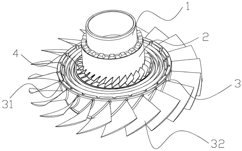
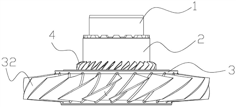
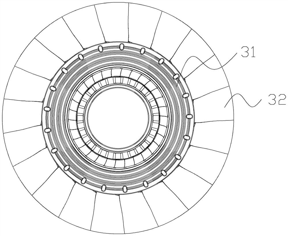
[0030] Such as Figure 1 to 6 As shown, the present invention provides a gas turbine compressor rotor seal strike structure, including a first cylinder 1, a second cylinder 2, and a third cylinder 3 that sequentially formed from top to bottom;

[0031] The diameter of the first cylinder 1 is smaller than the diameter of the second cylinder 2, the diameter of the second cylinder 2 is smaller than the diameter of the third cylinder 3, and the first cylinder 1, the second cylinder 2 And the interior of the third cylinder 3 is provided with a hollow region;

[0032] The side surface of the third cylinder 3 is provided with a main vane 31, and the top surface of the third cylinder 3 is provided with a cyclic oscillated tooth 31, and the ring jet 31 can be reduced, and the channel 500 can be reduced. The width, avoiding excessive gas streams into passage 500 due to the rotation of the sealing blade 4, producing a pneumatic loss, the junction ring of the top surface of the third cylinder ...

Embodiment 2

[0034] Such as Figure 1 to 6 As shown, the present invention provides a gas turbine compressor rotor seal strike structure, including a first cylinder 1, a second cylinder 2, and a third cylinder 3 that sequentially formed from top to bottom;

[0035] The diameter of the first cylinder 1 is smaller than the diameter of the second cylinder 2, the diameter of the second cylinder 2 is smaller than the diameter of the third cylinder 3, and the first cylinder 1, the second cylinder 2 And the interior of the third cylinder 3 is provided with a hollow region;

[0036] The side surface of the third cylinder 3 is provided with a main vane 31, and the top surface of the third cylinder 3 is provided with a cyclic oscillated tooth 31, and the ring jet 31 can be reduced, and the channel 500 can be reduced. The width, avoiding excessive gas streams into passage 500 due to the rotation of the sealing blade 4, producing a pneumatic loss, the junction ring of the top surface of the third cylinder ...


PUM


Abstract

The invention discloses a gas compressor rotor sealing structure for a gas turbine. The gas compressor rotor sealing structure is characterized by comprising a first cylinder, a second cylinder and a third cylinder which are sequentially manufactured into a whole from top to bottom, the diameter of the first cylinder is smaller than that of the second cylinder, the diameter of the second cylinder is smaller than that of the third cylinder, hollow areas are arranged in the first cylinder, the second cylinder and the third cylinder respectively, a main blade is annularly arranged on the side face of the third cylinder, an annular labyrinth is arranged on the top face of the third cylinder, a sealing blade is annularly arranged on one side, close to the second cylinder, of the top face of the third cylinder, and the rotating direction of the sealing blade is consistent with that of the main blade. According to the gas compressor rotor sealing structure for the gas turbine, the labyrinth and the sealing blades are arranged in a matched mode, it is guaranteed that gas is pressed from a low-pressure stage to a high-pressure stage, meanwhile, high-pressure-stage gas is prevented from flowing back, active sealing is carried out, pneumatic loss is reduced, and the efficiency of a gas compressor is improved.

Description

Technical field [0001] The present invention relates to the field of gas turbine technology, and more particularly to a gas turbine compressor rotor seal strike structure. Background technique [0002] The traditional rigidus structure is an axial jaw structure due to the problem of manufacturing difficulty, and some deformed structures based on this structure. [0003] At present, the rotor and the static sub-directional structure are long, the rumor is simple, the sealing effect is poor, the friction generated in the work can cause the sealing tooth to be permanently deformed, so that the amount of leakage is further increased, and the engine performance attenuation is accelerated; The 齿 is worn in the work, when the differential pressure is slightly large, the commonly used seal seal is easy to vibrate during the airflow leakage process. [0004] Based on the above, the present invention has proposed a gas turbine compressor rotor to seal the strike structure, which can effect...

Claims


Application Information

Patent Timeline
Patent Type & Authority Applications(China)
IPC IPC(8): F04D29/32F04D29/38F04D29/16
CPCF04D29/164F04D29/321F04D29/324
Inventor 韩品连胡辉
Owner ZHEJIANG YIDONG TECH CO LTD
Learn More