Optical equipment monitoring system

A technology of optical equipment and monitoring system, applied in general control system, control/adjustment system, program control, etc., can solve problems such as difficult precision detection and analysis, imperfect monitoring of optical equipment, etc., and achieve the effect of providing reliability

Pending Publication Date: 2021-07-16
CHANGCHUN INST OF OPTICS FINE MECHANICS & PHYSICS CHINESE ACAD OF SCI
View PDF0 Cites 0 Cited by
  • Summary
  • Abstract
  • Description
  • Claims
  • Application Information

AI Technical Summary

Problems solved by technology

Among them, the static accuracy is mostly detected by shooting stars, and the dynamic accuracy is mostly carried out in combination with missions for calibration and flight comparison. It is difficult to carry out quantitative accuracy detection and analysis in the field environment
Therefore, the current monitoring of optical equipment is not perfect, and there is room for improvement

Method used


Image

  • Optical equipment monitoring system
  • Optical equipment monitoring system
  • Optical equipment monitoring system

Examples


Embodiment Construction

[0029] In the following description, specific details such as specific system structures and technologies are presented for the purpose of illustration rather than limitation, so as to thoroughly understand the embodiments of the present invention. It will be apparent, however, to one skilled in the art that the invention may be practiced in other embodiments without these specific details. In other instances, detailed descriptions of well-known systems, devices, circuits, and methods are omitted so as not to obscure the description of the present invention with unnecessary detail.

[0030] In order to illustrate the technical solutions of the present invention, specific examples are used below to illustrate.

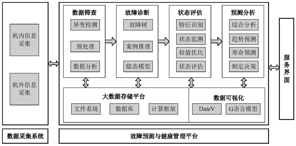
[0031] figure 1 It is a schematic flowchart of health management technology according to the prior art. like figure 1 As shown, the health management system mainly collects the parameter information (internal information) of each subsystem inside the optical equipmen...


PUM


Abstract

The invention provides an optical equipment monitoring system. The optical equipment monitoring system comprises a built-in test information acquisition device, an external test information acquisition device, a human-assisted acquisition input device, a monitoring device which is in communication connection with the built-in test information acquisition device, the external test information acquisition device and the human-assisted acquisition input device, and is configured to perform monitoring based on the built-in test information, the external test information and test point parameters, and a human-computer interaction interface which is in communication connection with the monitoring device so as to carry out real-time monitoring. According to the embodiment of the invention, the built-in test information, the external test information and the test point information can be comprehensively acquired, and the information can be monitored in real time by using convenient human-computer interaction. Therefore, the reliability of the monitoring is provided.

Description

technical field [0001] The invention belongs to the technical field of software development, in particular to an optical equipment monitoring system. Background technique [0002] The current health management system mainly collects the parameter information (internal information) of each subsystem inside the optical device (for example, theodolite) and the sensor parameter information (external information) placed at each key node of the system, and then screens the data. , diagnosis, analysis and other processing, complete the comprehensive health checkup and fault joint diagnosis of the whole system, and form a system health status resume to predict and evaluate the health status of the system. The health management system includes three parts: data acquisition system, fault prediction and health management platform, and service interface. [0003] The monitoring of many parameters of the optical system needs to be realized in combination with special optical detection e...

Claims


Application Information

Patent Timeline
Patent Type & Authority Applications(China)
IPC IPC(8): G05B19/048
CPCG05B19/048
Inventor 张甫恺崔明张维达
Owner CHANGCHUN INST OF OPTICS FINE MECHANICS & PHYSICS CHINESE ACAD OF SCI
Why Eureka
Try Eureka