Frame adhesive force testing equipment and testing method thereof

A test method and adhesive force technology, applied in measuring devices, instruments, mechanical devices, etc., can solve problems such as inaccurate test results of sealant, and achieve the effect of monitoring reliability

Active Publication Date: 2021-05-25
HUA WEI SEMICONDUCTOR (SHANGAHAI) CO LTD
View PDF8 Cites 0 Cited by
  • Summary
  • Abstract
  • Description
  • Claims
  • Application Information

AI Technical Summary

Problems solved by technology

One of the existing test methods for the adhesive force of the frame adhesive is: by manually breaking the semiconductor chip and the glass substrate (that is, manually separating the semiconductor chip from the glass substrate) to perceive the adhesive force of the adhesive frame; the second method is: through a tension ga

Method used


Image

  • Frame adhesive force testing equipment and testing method thereof
  • Frame adhesive force testing equipment and testing method thereof
  • Frame adhesive force testing equipment and testing method thereof

Examples


Embodiment 1

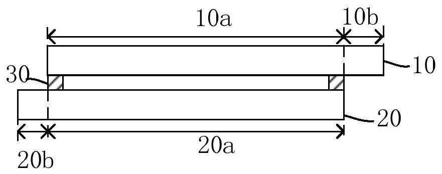
[0060] figure 1 It is a schematic diagram of the cross-sectional structure of the micro-chip of the first embodiment. Such as figure 1 As shown, the microscopic chip includes a cover plate 10 and a bottom plate 20. The cover plate 10 is, for example, a glass substrate, and the bottom plate 20 is, for example, a semiconductor chip. The cover plate 10 and the bottom plate 20 are connected by a sealant 30. Specifically, The cover plate 10 and the bottom plate 20 are connected in a closed ring shape on the opposite surfaces of the cover plate 10 and the bottom plate 20 through the frame glue 30 to seal the cover plate 10 and the bottom plate 20 surrounded by the frame glue 30 internal environment.

[0061] In this embodiment, a partial area of ​​the cover plate 10 and a partial area of ​​the bottom plate 20 are located outside the sealant 30 , and they are disposed on opposite sides of the sealant 30 . Specifically, the cover plate 10 includes a first area 10a and a second area...

Embodiment 2

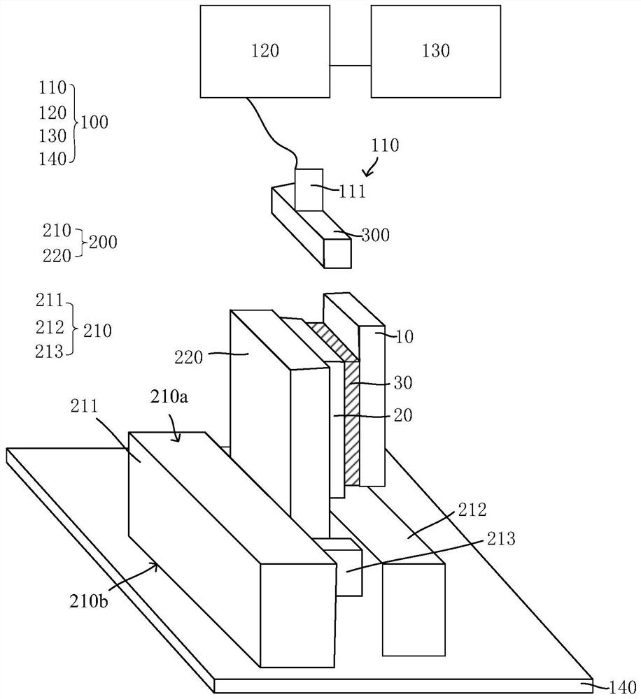
[0094] The difference between this embodiment and Embodiment 1 is that the surface of the cover plate of the microscopic chip away from the bottom plate is fixed on the working surface of the fixing unit 200, and the projection on the plane where the working surface is located is located at the work surface.

[0095] Specifically, the projection of the first area 20a on the plane of the work surface is located on the work surface, and the projection of the second area 20b on the plane of the work surface is located outside the work surface. During the frame glue adhesion test, on the surface of the bottom plate 20 facing the cover plate 10, the thrust unit 110 exerts a thrust away from the cover plate 10 on the bottom plate 20, so as to connect the frame glue The cover plate 10 and the bottom plate 20 are separated.

[0096] The second area 20b is located on the other three directions of the work surface except the side facing the support unit. Preferably, the second area 20b...

Embodiment 3

[0105] Figure 4 It is a schematic diagram of the cross-sectional structure of the micro-chip of this embodiment. Such as Figure 4As shown, the difference between the present embodiment and the first embodiment is that part of the base plate 20 of the frame adhesive adhesion testing device is located outside the frame adhesive 30, and at this time, the cover plate 10 only includes the second An area 10a, the bottom plate 20 includes a first area 20a and a second area 20b connected to each other, the cover plate 10, the first area 20a and the second area 20b are, for example, rectangular, and the first area 10a and The first area 20a overlaps and is closed by the sealant 20, and the second area 20b is exposed outside the sealant.

[0106] The surface of the cover plate of the microscopic chip away from the bottom plate is fixed on the working table of the fixing unit 200 , and the projection on the plane where the working table is located is located on the working table. Sp...


PUM


Abstract

According to a frame adhesive force testing equipment and the testing method thereof provided by the invention, the testing tool bit is driven by the thrust unit to get close to and push the cover plate or the bottom plate exposed out of the working table in the horizontal direction until the cover plate and the bottom plate which are connected through the frame adhesive are separated; therefore, the thrust provided by the thrust unit is performed along the horizontal direction, a product failure model is easy to simulate, and the reliability of the micro-display chip can be effectively monitored. Besides, according to the method for testing the adhesive force of the frame adhesive, the testing result of the adhesive force of the frame adhesive can be quantified, the testing accuracy and stability are improved, and establishment of a judgment standard of the adhesive force of the frame adhesive of the micro-display chip is facilitated.

Description

technical field [0001] The invention relates to the field of chip testing, in particular to a frame glue adhesion testing device for measuring microscopic chips and a testing method thereof. Background technique [0002] A microchip can be formed after the semiconductor chip is combined with the glass substrate through the frame glue, and the frame glue usually needs to be tested for the adhesion of the frame glue during the self-use test. One of the existing test methods for the adhesive force of the frame adhesive is: by manually breaking the semiconductor chip and the glass substrate (that is, manually separating the semiconductor chip from the glass substrate) to perceive the adhesive force of the adhesive frame; the second method is: through a tension meter Measure the adhesive force of the frame glue. Specifically, fix the semiconductor chip of the micro-chip on the base, and use a tension meter to pull the glass substrate vertically upwards to measure the adhesion of ...

Claims


Application Information

Patent Timeline
IPC IPC(8): G01N19/04
CPCG01N19/04
Inventor 高冠龙许冠军
Owner HUA WEI SEMICONDUCTOR (SHANGAHAI) CO LTD
Why Eureka
Try Eureka