Exhaust assembly of flat-panel display
A flat-panel display and component technology, which is applied in the direction of electrical components, electrical equipment structural parts, cooling/ventilation/heating transformation, etc., can solve the problem of entering the interior of the flat-panel display, failure of the flat-panel display, and backflow of the exhaust pipe into the interior of the flat-panel display, etc. question
- Summary
- Abstract
- Description
- Claims
- Application Information
AI Technical Summary
Problems solved by technology
Method used
Image

Examples
Embodiment 1
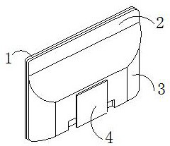
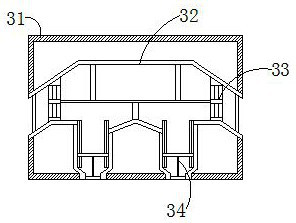
[0022] as attached figure 1 to attach Figure 4 Shown:
[0023] The present invention is an exhaust assembly of a flat panel display, the structure of which comprises a display screen 1, a back plate 2, an exhaust mechanism 3, and a stabilizing block 4, the rear end of the display screen 1 is welded on the front surface of the back plate 2, and the back plate 2 The rear end surface is provided with an exhaust mechanism 3, and the middle end of the exhaust mechanism 3 is embedded with a stabilizing block 4. The exhaust mechanism 3 includes a casing 31, an exhaust pipe 32, a dustproof device 33, a heat dissipation device 34, the exhaust pipe 32 runs through the middle end of the shell 31, the left and right ends of the exhaust pipe 32 are provided with dustproof devices 33, and the lower end of the exhaust pipe 32 is fixedly installed with a heat sink 34, and the heat dissipation The device 34 is installed at the lower end of the dustproof device 33 , the inner bottom of the h...
Embodiment 2
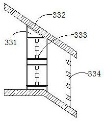
[0029] as attached Figure 5 to attach Figure 7 Shown:
[0030] Wherein, the heat dissipation device 34 includes a support plate 341, a cooling device 342, a drainage device 343, a bracket 344, a fixed buckle 345, a sliding shaft 346, a chute 347, a spring 348, a connecting rod 349, and a blocking block 340. The lower end of 341 is provided with a cooling device 342, the cooling device 342 is installed on the upper end of the drainage device 343, the middle part of the lower end of the drainage device 343 is provided with a bracket 344, the sliding shaft 346 is engaged with the chute 347, and the fixed buckle The left and right ends of 345 are connected with the sliding shaft 346, the lower end of the middle part of the fixed buckle 345 is welded with a connecting rod 349, the lower end of the sliding shaft 346 is welded with a spring 348, and the lower end of the connecting rod 349 is connected with a blocking block 340, the The inner bottom of the shell 31 is provided wit...
PUM
 Abstract
Description
Claims
Application Information