
A control structure and construction method for overrun convergence deformation of shield tunnel during operation period

A shield tunneling and convergence deformation technology, which is applied in tunnels, tunnel linings, earthwork drilling and mining, etc., can solve problems such as segment cracks or misalignment, segment fragmentation, and shield tunnel convergence deformation diseases, so as to prevent deformation and Misalignment or partial damage, increase the contact area, and increase the effect of pulling out

Active Publication Date: 2022-04-26
江苏中车城市发展有限公司 +2
View PDF7 Cites 0 Cited by
  • Summary
  • Abstract
  • Description
  • Claims
  • Application Information

AI Technical Summary

Problems solved by technology

All of the above situations may lead to convergence deformation of the shield tunnel
The convergence deformation of the shield tunnel will cause cracks or dislocation between the segments, and in severe cases, it will lead to bolt breakage, joint damage, partial fragmentation of segments, crack expansion and other diseases in the shield tunnel, and even damage to the main structure of the tunnel. Threats to the operational safety of trains or vehicles in shield tunnels
At present, the research and development of shield tunnel convergence deformation control technology is mainly focused on the monitoring and prediction of convergence deformation, that is, through the accurate real-time monitoring of shield tunnel convergence deformation during construction and operation periods, the convergence deformation of shield tunnels can be realized. effective prevention of shield tunneling, but there is still a lack of control technology for shield tunnel overrun convergence deformation

Method used


Image

  • A control structure and construction method for overrun convergence deformation of shield tunnel during operation period
  • A control structure and construction method for overrun convergence deformation of shield tunnel during operation period
  • A control structure and construction method for overrun convergence deformation of shield tunnel during operation period

Examples


Embodiment Construction

[0037] The present invention will be described in further detail below in conjunction with the accompanying drawings and embodiments.

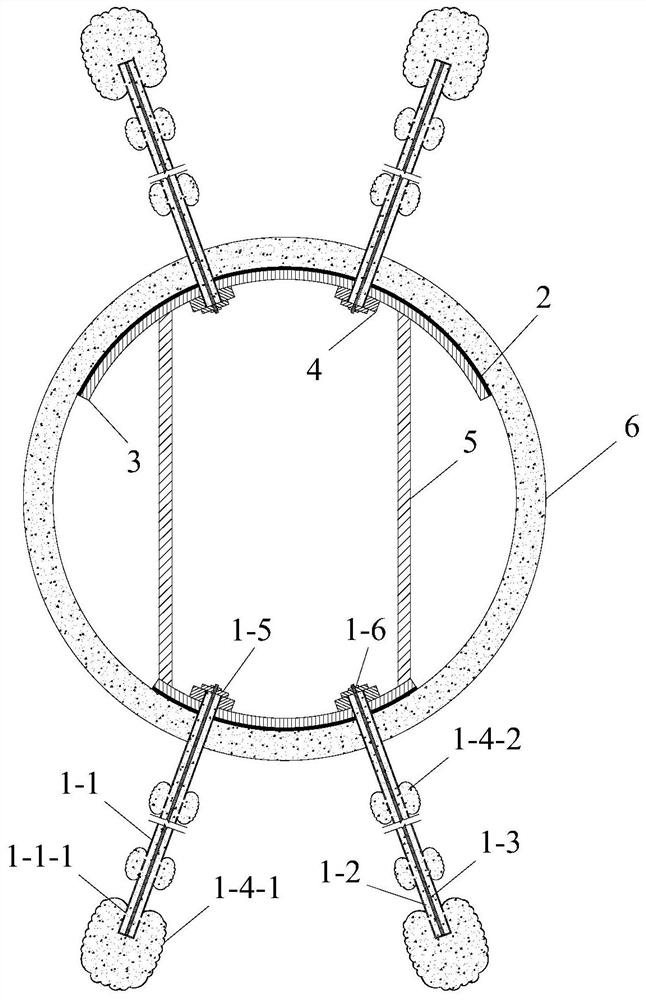
[0038] Such asfigure 1 As shown, this embodiment provides a governance structure for overrun convergence deformation of a shield tunnel during the operation period, including a bag-expanded prestressed anchor rod 1, a waterproof layer 2, a circumferential steel beam 3, a longitudinal steel beam 4 and a pair of Support truss 5.

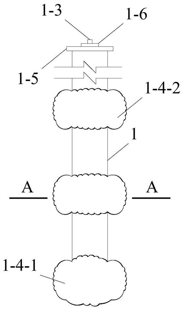
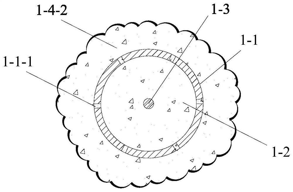
[0039] Such as figure 2 , 3 As shown, the bladder expansion type prestressed anchor 1 is composed of a bladder expansion type prestressed anchor body 1-1, a grouting body 1-2, a prestressed steel bar 1-3 and a grouting bladder; The main body 1-1 of the enlarged prestressed anchor rod of the bladder bag is staggered and runs through the uniformly distributed grouting holes 1-1-1 in the circumferential direction; Slurry 1-2 and prestressed reinforcement 1-3.

[0040] The grouting bag includes a terminal grouting bag...


PUM


Abstract

The invention discloses a control structure and a construction method for over-limit convergence deformation of a shield tunnel during the operation period. The structure includes a bag-expanded prestressed anchor rod, a waterproof layer, a circumferential steel beam, a longitudinal steel beam, and a paired truss ;The contact area between the expanded bladder prestressed anchor rod and the surrounding soil layer of the shield tunnel is increased by the enlarged bladder, and the pull-out resistance is increased. The expanded bladder prestressed anchor rod symmetrically arranged on the section of the shield tunnel The application of the prestressing force and the application of the jack reaction force to the support truss, the two work together, can effectively control the over-limit convergence deformation of the section of the shield tunnel, and resume the operation of the shield tunnel as soon as possible; after the section of the shield tunnel returns to normal, the capsule The expanded prestressed anchor will continue to be used normally, effectively serving the prevention and control of convergence deformation during the entire life cycle of the shield tunnel in operation.

Description

technical field [0001] The invention relates to the technical field of convergence deformation control of shield tunnels, in particular to a control structure and a construction method for excessive convergence deformation of shield tunnels during operation. Background technique [0002] Based on the advantages of shield method, such as safety, rapidity, high efficiency, environmental protection and strong adaptability, urban rail transit projects in my country mainly use this method for construction. [0003] The main body of the shield tunnel is the shield segment, which is subjected to (super) high water and soil pressure and complex hydrogeological environment during long-term service, which has high requirements on the quality and durability of the segment; on the other hand, in The operation stage of the shield tunnel is susceptible to some uncertain factors, for example, soil disturbance and loading caused by changes in surrounding hydrogeological conditions, close co...

Claims


Application Information

Patent Timeline
Patent Type & Authority Patents(China)
IPC IPC(8): E21D21/00E21D20/02E21D11/00E21D11/08E21D11/18E21D11/28E21D11/38
CPCE21D21/0026E21D21/0093E21D20/02E21D20/028E21D11/00E21D11/38E21D11/18E21D11/183E21D11/28E21D11/08
Inventor 刘小荣吴增金汪安祥蒋志华孟晨曦齐士乐苏光旭刘念武
Owner 江苏中车城市发展有限公司
Learn More