Device applied to high-speed line scanning detection and detection method thereof

A detection device and high-speed line technology, which is applied to measuring devices, optical devices, instruments, etc., can solve problems such as difficult operation, unclear image acquisition, and inability to have both brightness and directionality of the light source at the same time, so as to reduce acquisition exposure time, improve the efficiency of visual inspection, and increase the effect of light efficiency utilization

Pending Publication Date: 2021-07-20
GUANGDONG AOPUTE TECH CO LTD
View PDF0 Cites 1 Cited by
  • Summary
  • Abstract
  • Description
  • Claims
  • Application Information

AI Technical Summary

Problems solved by technology

[0003] In the prior art, the coaxial light source used for thermal detection of mobile phone flexible screens cannot have both the brightness and directionality of the light source at the same time. The existing coaxial light source is either high in brightness, poor in directionality, and requires multiple manual adjustments of the light source. , so that the directionality meets the shooting requirements, the operation is difficult, and the image acquisition speed is low; or the directionality is good, but the brightness of the light source is low, resulting in insufficient brightness of the light source lighting unit, and the image acquisition is not clear

Method used


Image

  • Device applied to high-speed line scanning detection and detection method thereof

Examples


Embodiment 1

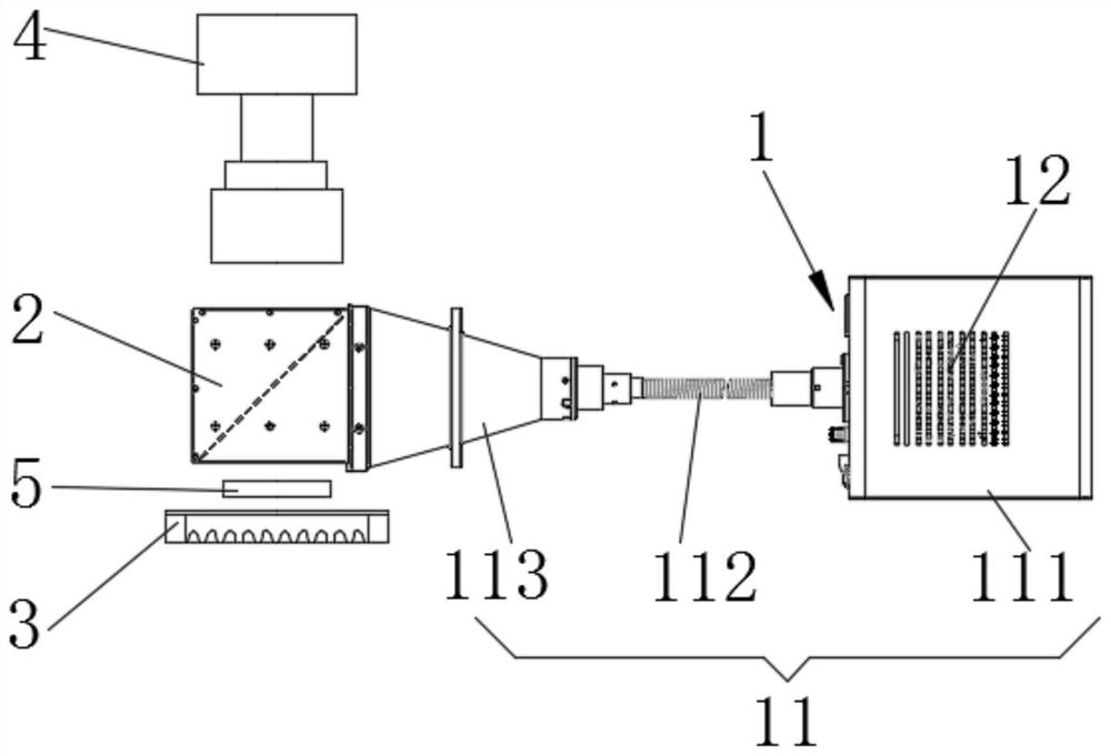
[0037] Such as figure 1 As shown, a device for high-speed line-scan detection includes a parallel light source device 1, a beam splitter 2, a backlight 3 and a camera 4. The beam splitter 2 is obliquely arranged at one end of the parallel light source device 1. The beam splitter 2, the backlight 3 and camera 4 are arranged in a line. The parallel light source device 1 adopts a telecentric optical path design, so that the parallelism of the outgoing light is high, and it is convenient to realize rapid detection. For example, when testing the heat of the mobile phone's flexible screen, the device can be used to image the slightly raised area caused by the heat of the mobile phone's flexible screen, and quickly capture and shoot. At the same time, due to the high parallelism and ultra-high brightness of the light generated by the device, it can make the lens light pass through more and reduce the acquisition and exposure time required by the camera 4. Compared with ordinary coax...

Embodiment 2

[0051] This embodiment 2 provides a detection method applied to high-speed line scanning, which adopts a device applied to high-speed line scanning detection in embodiment 1 for detection, as follows:

[0052] Step 1: Adjust the relative positions of the parallel light source device (1), the beam splitter (2), the backlight source (3) and the camera (4), and turn on the parallel light source device (1), so that the light spot falls on the front view of the camera (4) middle;

[0053] Step 2: Connect the camera (4) to the computer, open the camera acquisition software, and set the exposure time;

[0054] Step 3: The product to be inspected (5) moves at a constant speed above the backlight source (3), and the camera (4) takes pictures of the product (5) to be inspected.

[0055] The camera (4) of above-mentioned step 3 takes pictures of the product (5) to be detected, which is as follows:

[0056] Step 3-1: The camera (4) locates the outer contour of the product (5) to be dete...


PUM


Abstract

The invention belongs to the technical field of machine vision, and particularly discloses a device applied to high-speed line scanning detection and a detection method thereof. The device comprises a parallel light source device, a spectroscope, a backlight source and a camera, the spectroscope is obliquely arranged at one end of the parallel light source device, and the spectroscope, the backlight source and the camera are linearly arranged. The device adopts the telecentric light path design of the parallel light source device, has the characteristics of high emergent light parallelism and ultrahigh brightness, can enable the light flux of the lens to be more, increases the light efficiency utilization rate, reduces the required camera acquisition exposure time, and greatly improves the visual inspection efficiency.

Description

technical field [0001] The invention belongs to the technical field of machine vision, and in particular relates to a device applied to high-speed line scan detection and a detection method thereof. Background technique [0002] With the rapid development of automatic optical inspection technology, the market demand for detection stability and detection efficiency is getting higher and higher. During high-speed detection, the stability of visual imaging effect and the speed of detection are two important factors that affect the detection efficiency. For example, during the thermal inspection of the flexible screen of a mobile phone, after the flexible screen passes through the laser cutting screen, due to the influence of laser heat near the cutting line, the area next to it will melt and produce a slight bump. In order to evaluate the size of the bumps, it is necessary for the camera to capture the flexible screen of the mobile phone and image the heat-affected area of ​​t...

Claims


Application Information

Patent Timeline
Patent Type & Authority Applications(China)
IPC IPC(8): G01B11/24
CPCG01B11/24
Inventor 谢春林张腾飞
Owner GUANGDONG AOPUTE TECH CO LTD
Why Eureka
Try Eureka