Laser signal control method and device, laser and readable storage medium

A laser signal and control method technology, applied in the field of lasers, can solve problems such as easily damaged laser components, and achieve the effect of weakening spontaneous radiation and preventing damage

Active Publication Date: 2021-07-20
深圳市欧凌镭射科技有限公司 +2
View PDF9 Cites 1 Cited by
  • Summary
  • Abstract
  • Description
  • Claims
  • Application Information

AI Technical Summary

Problems solved by technology

[0005] The embodiment of the present application provides a laser signal control method, device, laser and readable storage medium, which can solve the problem that the current laser signal control method is easy to damage the laser components to a certain extent

Method used


Image

  • Laser signal control method and device, laser and readable storage medium
  • Laser signal control method and device, laser and readable storage medium
  • Laser signal control method and device, laser and readable storage medium

Examples


Embodiment 1

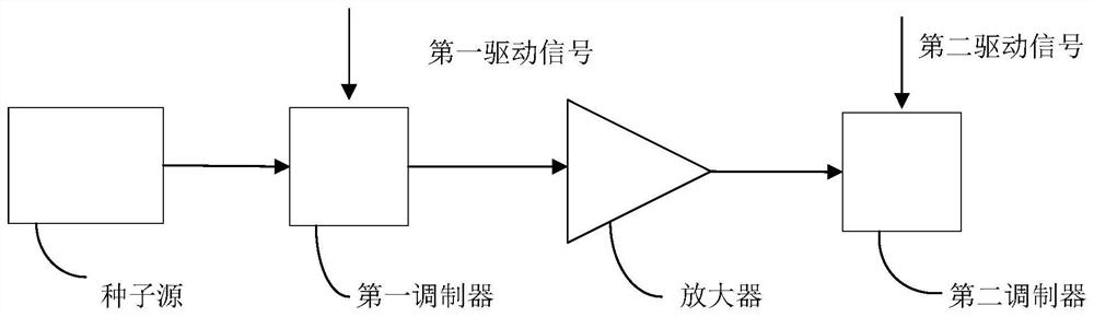
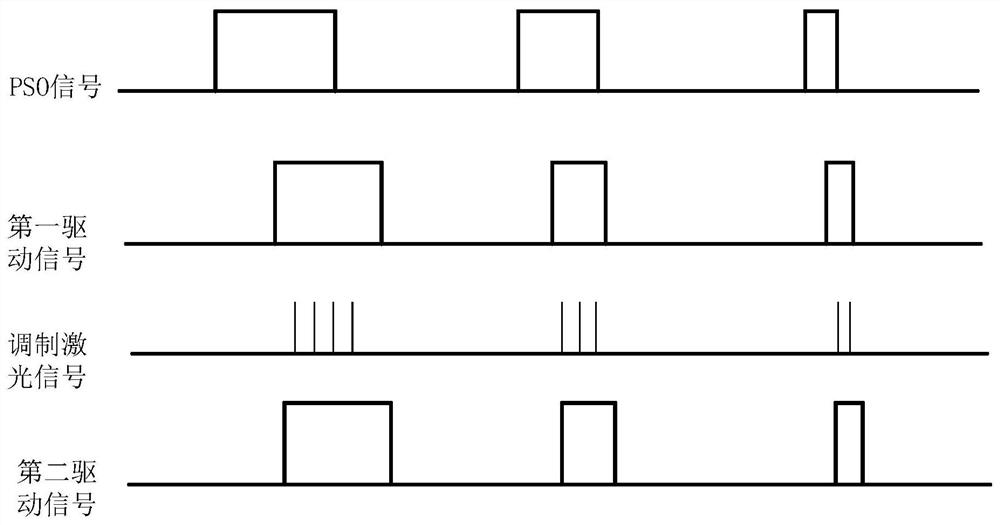
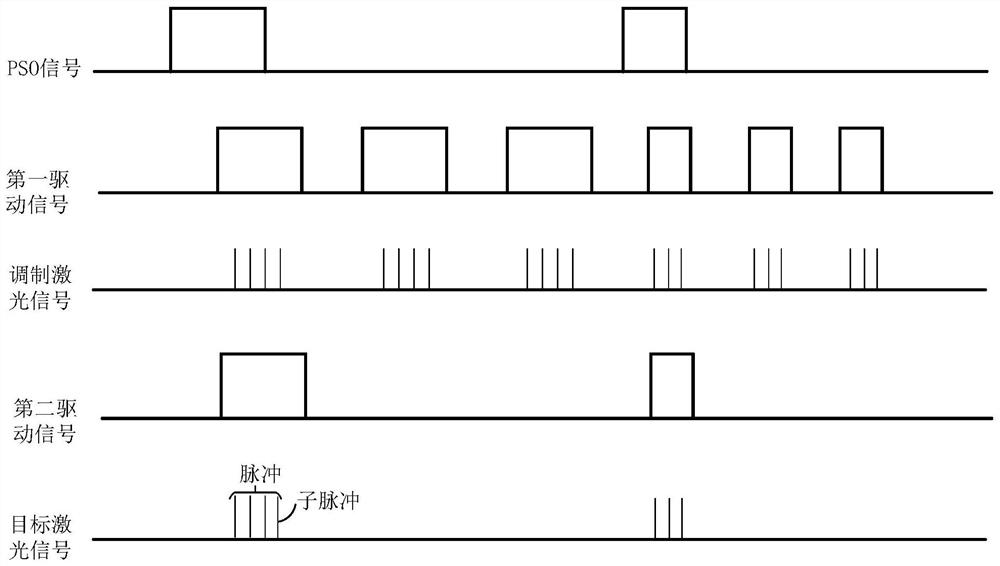
[0054] The composition of the laser is generally as follows figure 1 shown. At present, when marking with a laser, the processing control system first generates the first driving signal and the second driving signal according to the PSO signal, and then sends the first driving signal and the second driving signal to the laser control board.

[0055] After receiving the first driving signal and the second driving signal, the laser control board first drives the first modulator according to the first driving signal to select the frequency of the seed optical signal to obtain the modulated laser signal. At this time, the frequency of the modulated laser signal generally decreases It is tens of kHz to several MHz, and the frequency of the seed optical signal is generally 30-50MHz. Therefore, the frequency of the modulated laser signal is reduced compared to the frequency of the seed light.

[0056] Since the frequency of the modulated laser signal drops, if the first frequency o...

Embodiment 2

[0098] Figure 7 An example of a laser signal control device is shown, and for the convenience of description, only parts related to the embodiment of the present application are shown. The device 700 includes:

[0099] A signal acquisition module 701, configured to acquire a first driving signal and a second driving signal, wherein the first driving signal includes several first trigger signals, the second driving signal includes several second trigger signals, and the first trigger signal of the first trigger signal A frequency is higher than a second frequency of the second trigger signal.

[0100] The first modulation module 702 is configured to drive the first modulator according to the first driving signal to modulate the seed optical signal to obtain a modulated laser signal.

[0101] The signal amplification module 703 is configured to input the modulated laser signal into the amplifier to obtain the amplified laser signal.

[0102] The second modulation module 704 ...

Embodiment 3

[0121] Figure 8 is a schematic diagram of the laser provided in Embodiment 3 of the present application. Such as Figure 8 As shown, the laser 800 of this embodiment includes: a processor 801 , a memory 802 , and a computer program 803 stored in the memory 802 and operable on the processor 801 . When the processor 801 executes the computer program 803, the steps in the above method embodiments are implemented. Alternatively, when the processor 801 executes the computer program 803, the functions of the modules / units in the above device embodiments are implemented.

[0122] Exemplarily, the above-mentioned computer program 803 may be divided into one or more modules / units, and the above-mentioned one or more modules / units are stored in the above-mentioned memory 802 and executed by the above-mentioned processor 801 to complete the present application. The above-mentioned one or more modules / units may be a series of computer program instruction segments capable of accomplish...


PUM


Abstract

The invention is suitable for the technical field of lasers, and provides a laser signal control method and device, a laser and a readable storage medium, the method comprises the following steps: obtaining a first driving signal and a second driving signal, wherein the first driving signal comprises a plurality of first trigger signals, the second driving signal comprises a plurality of second trigger signals, the first frequency of the first trigger signal is higher than the second frequency of the second trigger signal; driving a first modulator to modulate the seed optical signal according to the first driving signal to obtain a modulated laser signal; inputting the modulated laser signal into an amplifier to obtain an amplified laser signal; and driving a second modulator to modulate the amplified laser signal according to the second driving signal to obtain a target laser signal. The problem that a laser element is easily damaged by an existing laser signal control method can be solved to a certain extent.

Description

technical field [0001] The present application belongs to the field of lasers, and in particular relates to a control method and device for laser signals, a laser and a readable storage medium. Background technique [0002] With the development of science and technology, the performance of lasers is getting better and better, and the application of lasers is becoming more and more extensive. For example, lasers are used for marking. [0003] At present, when marking with a laser, the position synchronization mode (Position Synchronized Output, PSO) is generally used, that is, when a target position is reached, a PSO signal is sent to make the laser emit light. However, at present, since the frequency of the first driving signal controlling the first modulator is consistent with the frequency of the PSO signal, the power of the laser signal after passing through the first modulator is relatively low, while the power of the pump light in the amplifier is generally fixed At t...

Claims


Application Information

Patent Timeline
Patent Type & Authority Applications(China)
IPC IPC(8): H01S3/09H01S3/10H01S3/11
CPCH01S3/09H01S3/10084H01S3/11
Inventor 李凯杨正宇罗近雅向杰
Owner 深圳市欧凌镭射科技有限公司
Why Eureka
Try Eureka