
Semiconductor light emitting device

a technology of semiconductor photodetector and light emitting device, which is applied in the direction of solid-state devices, lasers, semiconductor lasers, etc., can solve the problems of insufficient improvement of light detection precision, effectively suppressed and improve the light detection precision further. , the effect of lowering the detection level of spontaneous emission light to the semiconductor photodetector

Active Publication Date: 2009-10-13
SONY CORP
View PDF8 Cites 4 Cited by
  • Summary
  • Abstract
  • Description
  • Claims
  • Application Information

AI Technical Summary

Benefits of technology

This configuration significantly improves light detection precision by reducing the detection level of spontaneous emission light, ensuring accurate measurement of the light output level and enhancing the reliability of the semiconductor light emitting device.

Problems solved by technology

Therefore, the technique of Japanese Patent No. 2,877,785 does not sufficiently lower the spontaneous emission light detection level of the semiconductor photodetector and has a disadvantage such that the light detection precision may not be sufficiently improved.

Method used


Image

  • Semiconductor light emitting device
  • Semiconductor light emitting device
  • Semiconductor light emitting device

Examples


first embodiment

Modification of First Embodiment

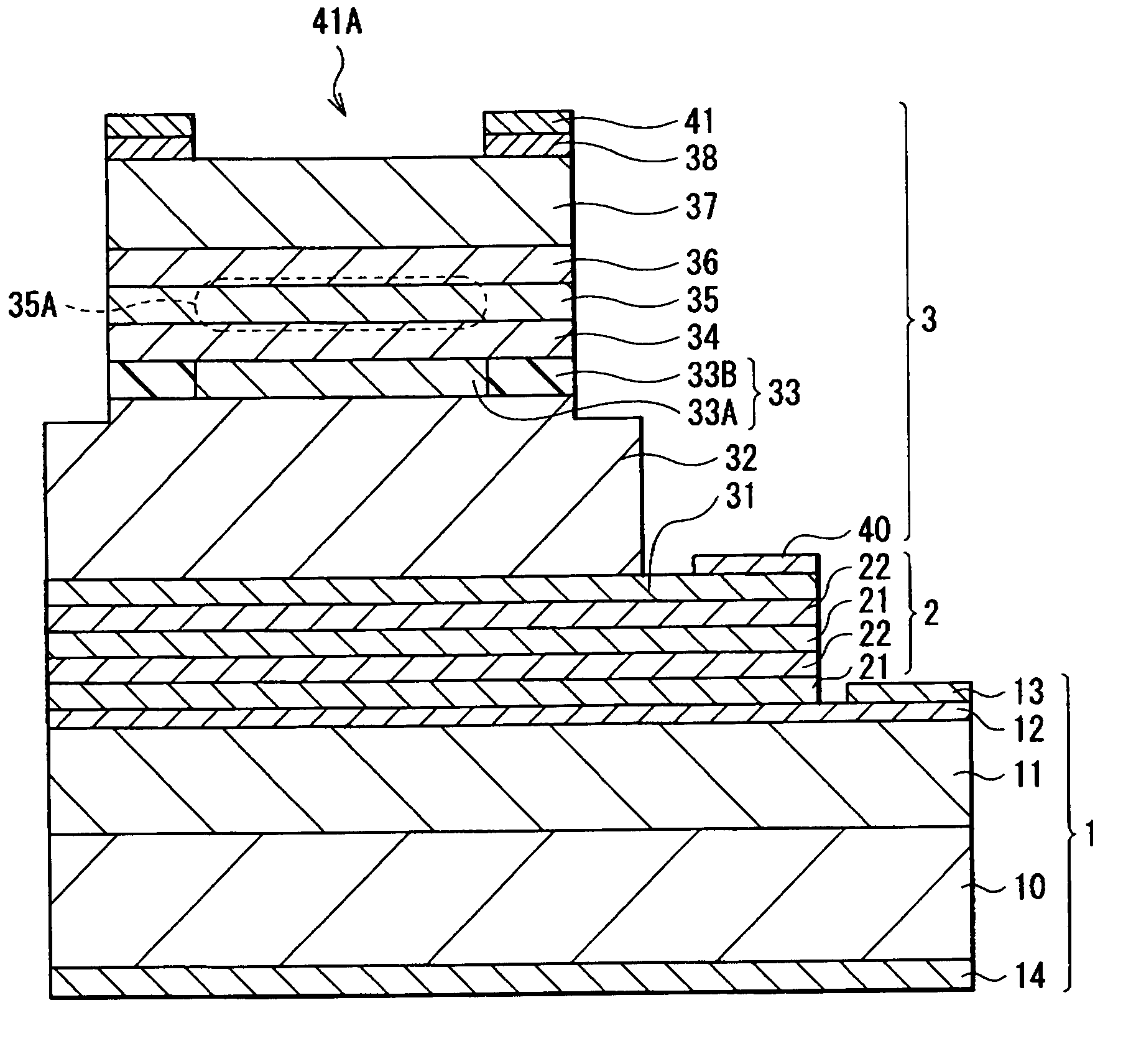
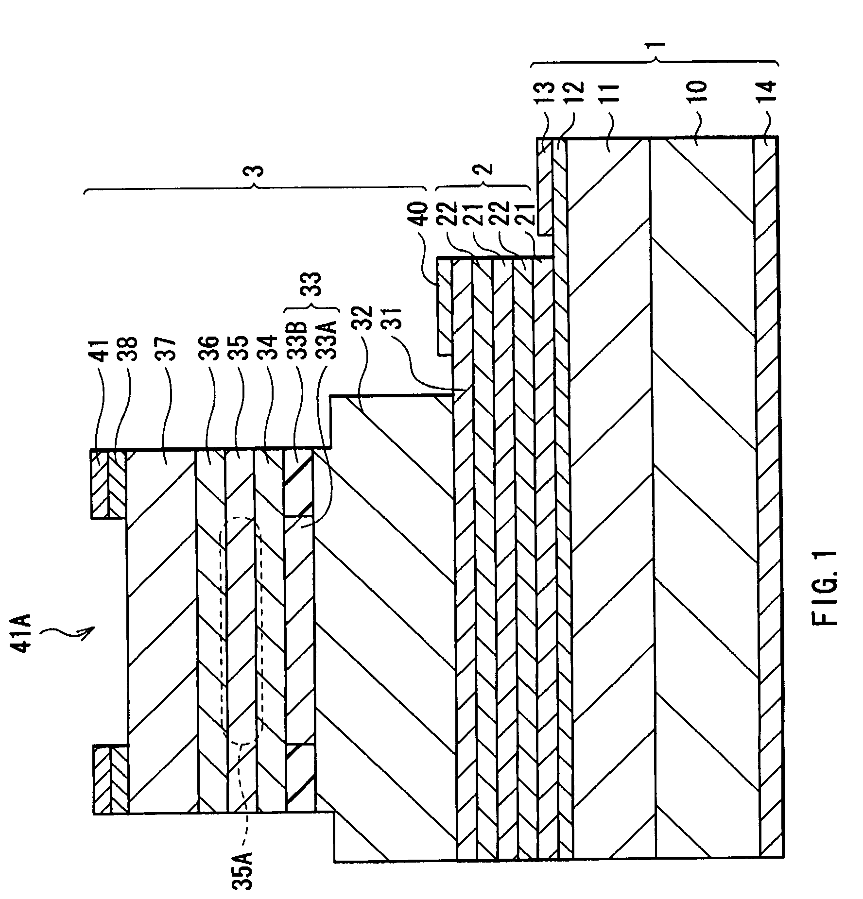
[0067]In the foregoing embodiment, the case has been described in which the multilayer filter 2 reflects light having a wavelength shorter than the wavelength λo in the spontaneous emission light L2 included in light output from the VCSEL 3 to the semiconductor photodetector 1 side. The multilayer filter 2 may reflect not only light having a wavelength shorter than the wavelength λo in the spontaneous emission light L2 included in light output from the VCSEL 3 to the semiconductor photodetector 1 side but also light having a wavelength longer than the wavelength λo.

[0068]In this case, it is sufficient to provide the multilayer filter 2 with not only the stack structure obtained by alternately stacking the low-refractive-index layers 21 made of, for example, p-type Alx13Ga1-x13As and each having a thickness of λ1 / 4n5 and the high-refractive-index layers 22 made of, for example, p-type Alx14Ga1-x14As and each having a thickness of λ1 / 4n6 but also, on or...

second embodiment

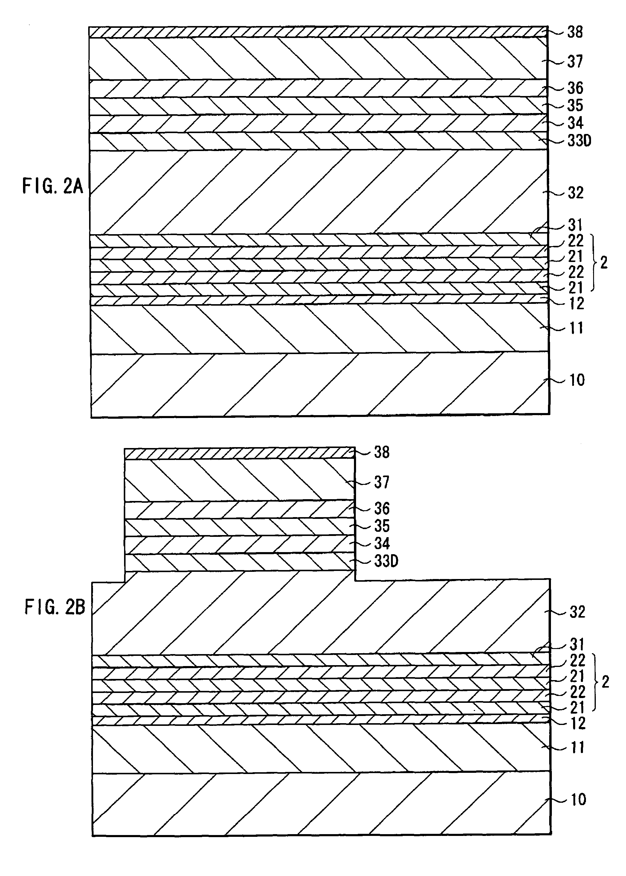
[0070]FIG. 8 shows the structure of a semiconductor light emitting device as a second embodiment of the present invention. FIG. 8 is a schematic diagram, and the dimensions and shapes in FIG. 8 are different from the actual ones. In the following description, when the same reference numeral as that in the foregoing embodiment is used, it means that the component has a configuration and function similar to those of the component having the same reference numeral. The configurations, operations, and effects that are different from those of the foregoing embodiment will be described mainly below. Descriptions of configurations, operations, and effects similar to those of the foregoing embodiment will not be repeated.

[0071]The semiconductor light emitting device is formed by bonding the multilayer filter 2 formed on one of the semiconductor photodetector 1 and the VCSEL 3 to the other one on which the multilayer filter 2 is not formed.

[0072]The semiconductor light emitting device is obt...


PUM


Abstract

The present invention provides a semiconductor light emitting device realizing a lower detection level of spontaneous emission light by a semiconductor photodetector and an improvement in light detection precision by selectively reflecting spontaneous emission light. The semiconductor light emitting device includes a semiconductor light emitting element for generating light including stimulated emission light having a wavelength lambdao and spontaneous emission light having a wavelength band including the wavelength lambdao, a multilayer filter having a stack structure in which a low-refractive-index layer having a thickness of lambda1 / (4xna) (lambda1<lambdao and na denote refractive index) and a high-refractive-index layer having a thickness of lambda1 / (4xnb) (nb>na and nb denote refractive index) are alternately stacked, and a semiconductor photodetector having a light absorption layer that absorbs part of the light passed through the multilayer filter.

Description

CROSS REFERENCE TO RELATED APPLICATIONS[0001]The present invention contains subject matter related to Japanese Patent Application JP 2007-096653 filed in the Japanese Patent Office on Apr. 2, 2007, the entire contents of which are incorporated herein by reference.BACKGROUND OF THE INVENTION[0002]1. Field of the Invention[0003]The present invention relates to a semiconductor light emitting device having a photodetector for detecting emitted light and, more particularly, to a semiconductor light emitting device which can be suitably applied to uses requesting a high-degree light detection precision.[0004]2. Description of the Related Art[0005]Up to this time, in a semiconductor light emitting device for the use of an optical fiber, an optical disk, and the like, as part of the object of making the light output level of a semiconductor light emitting element assembled in the device constant, emission light of the semiconductor light emitting element was detected by a light detecting me...

Claims


Application Information

Patent Timeline
Patent Type & Authority Patents(United States)
IPC IPC(8): H01L27/15H01L29/26H01L31/12H01L33/00H01S5/026H01S5/183
CPCH01L27/15H01S5/18311H01L33/02H01S5/0264H01S5/0078
Inventor KODA, RINTAROARAKIDA, TAKAHIROMASUI, YUJIOKI, TOMOYUKI
Owner SONY CORP
Learn More