Fluid mixing device

A fluid mixing and melt mixing technology, applied in fluid mixers, mixers, transportation and packaging, etc., can solve the problems of a large proportion of stirring dead zone, the area cannot be mixed evenly, and the mixture is difficult to turn over and mix. Eliminate the dead zone of mixing, enhance the degree of confusion, and improve the effect of mixing uniformity

Active Publication Date: 2021-07-23
浙江华油色纺科技有限公司
View PDF8 Cites 0 Cited by
  • Summary
  • Abstract
  • Description
  • Claims
  • Application Information

AI Technical Summary

Problems solved by technology

[0002] In the industrial production of the chemical industry, especially in the production of plastics, dyes, fabrics and other industries, it is often necessary to mix two or more fluid materials in molten state or solution, and the uniformity of mixing has always affected the product effect. An important factor. At present, in industrial production, mixing is often carried out by means of free diffusion of liquid, mixing and stirring, and vibration of the mixing container. However, these mixing methods inevitably have a stirring dead zone, which leads to the problem that some areas cannot be mixed uniformly.
[0003] And for the fine chemical industry, the amount of materials to be mixed may be small and the ingredients are large. When mixing in a traditional way, it is difficult to fully turn over and mix a small amount of mixture, the degree of chaos is small, and the proportion of the dead zone of mixing will be larger. lead to an increase in product failure rate

Method used


Image

  • Fluid mixing device
  • Fluid mixing device
  • Fluid mixing device

Examples


Embodiment 1

[0040] The mixed material used in this embodiment takes melt 9 as an example.

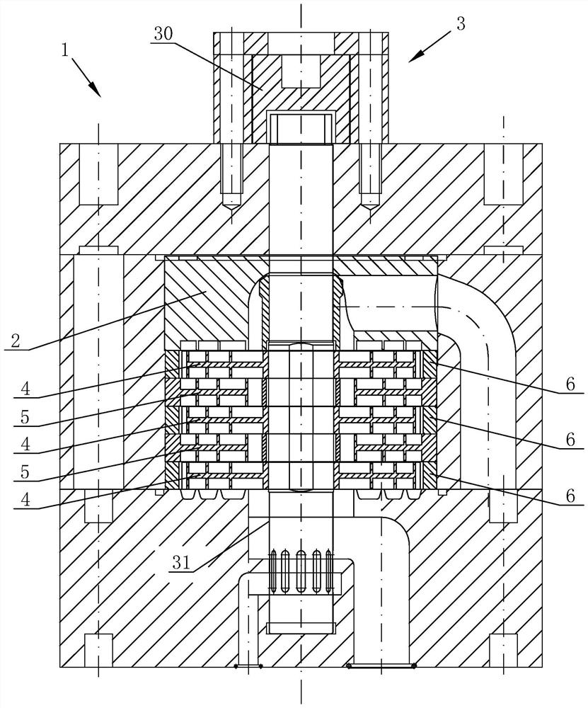
[0041] Such as figure 1 The fluid mixing device shown includes a mixing container 1, a feeding cover 2, a mixing mechanism and a driving mechanism 3 for guiding the mixing of the melt 9, and the melt 9 containing various components enters the mixing container 1 from the feeding cover 2 The homogenization process is carried out by the mixing mechanism.

[0042] The mixing mechanism includes three first material guide discs 4, two second material guide discs 5 and three annular baffles 6, the first material guide discs 4 and the second material guide discs 5 are alternately arranged up and down, the uppermost layer and the lowermost layer Both are first material guide discs 4 , that is, two second material guide discs 5 are interposed between three first material guide discs 4 , and annular baffles 6 are sheathed on the outer circumference of the first material guide discs 4 .

[0043] The driving ...

Embodiment 2

[0055] Such as Figure 18 As shown, this embodiment is based on the technical solution of Embodiment 1, and the technical points of difference between this embodiment and Embodiment 1 are:

[0056] The annular material guide groove 7 has three layers in total, wherein the material guide grid 71 of the annular material guide groove 7 in the middle is provided with an X-shaped deflector 10, and the four ends of the X-shaped deflector 10 are respectively arranged on the material guide. At the four corners of the lattice 71, the X-shaped deflector 10 can guide the melt 9 to flow in a path with a larger span, and the melt 9 in the A material guide lattice 71 can flow through the X-shaped deflector 10 and flow to A 1 Guide grid 71 and A 2 Material guide grid 71, the melt 9 in the B material guide grid 71 can flow through the X-shaped deflector 10 and flow to B 1 Guide grid 71 and B 2 The material guide grid 71, and the melt 9 from adjacent A and B material guide grids 71 ​​can cr...


PUM


Abstract

The invention discloses a fluid mixing device, which aims to improve the melt mixing uniformity, and adopts the main technical scheme that the fluid mixing device comprises a mixing container, a feeding cover, a mixing mechanism and a driving mechanism, the mixing mechanism comprises a first material guide disc, a second material guide disc and an annular baffle plate, the first material guide disc is provided with a fixing hole and a plurality of layers of annular material guide grooves, the annular guide grooves are divided into a plurality of guide grids by partition plates arranged at equal intervals in the circumferential direction, the adjacent annular guide grooves are separated through annular walls, the guide grids on the inner layer and the outer layer are arranged in a staggered mode, and a plurality of grooves are formed in the side wall of the outer edge of the first guide disc; the second material guide disc is provided with a flow guide hole and a plurality of layers of annular material guide grooves with the same structure as the first material guide disc, and the outer edge of the second material guide disc is an annular sealing edge; the lower surface of the feeding cover is provided with a plurality of layers of annular guide grooves with the same structure as the first guide disc and the second guide disc, and the first guide disc and the second guide disc are alternately arranged up and down; the driving mechanism is provided with a rotating rod penetrating through the fixing hole and the flow guide hole, and the first material guide disc is relatively and fixedly connected with the rotating rod.

Description

technical field [0001] The invention relates to the field of material mixing equipment, in particular to a fluid mixing device. Background technique [0002] In the industrial production of the chemical industry, especially in the production of plastics, dyes, fabrics and other industries, it is often necessary to mix two or more fluid materials in molten state or solution, and the uniformity of mixing has always affected the product effect. An important factor. At present, in industrial production, mixing is often carried out by means of free diffusion of liquid, mixing and stirring, and vibration of the mixing container. However, these mixing methods inevitably have a stirring dead zone, which leads to the problem that some areas cannot be mixed evenly. [0003] And for the fine chemical industry, the amount of materials to be mixed may be small and the ingredients are large. When mixing in a traditional way, it is difficult to fully turn over and mix a small amount of mix...

Claims


Application Information

Patent Timeline
Patent Type & Authority Applications(China)
IPC IPC(8): B01F5/00
CPCB01F25/00B01F2025/93
Inventor 张建梁刘增川
Owner 浙江华油色纺科技有限公司
Why Eureka
Try Eureka