Method for designing sliding bearing of supergravity centrifugal machine based on vibration control

A sliding bearing and vibration control technology, applied in the direction of centrifuges, sustainable transportation, etc., can solve the impact of the dynamic response of the rotor system without considering the bearing support stiffness, immature design and use of sliding bearings in supergravity centrifuges, Problems such as high rotor vibration quality requirements, to achieve the effect of improving work quality, ensuring effective implementation, and reducing potential safety hazards

Active Publication Date: 2021-07-23
ZHEJIANG UNIV
View PDF9 Cites 0 Cited by
  • Summary
  • Abstract
  • Description
  • Claims
  • Application Information

AI Technical Summary

Problems solved by technology

[0014] (1) Existing safety assessments or tests on supergravity centrifuges are based on the rolling bearing support structure, without considering the impact of bearing support stiffness on the dynamic response of the rotor system, and there is no such thing as a sliding bearing support supergravity centrifuge safety assessment plan;
[0015] (2) The design and application of sliding bearings is mainly based on the mature experience of water turbines, but the load conditions of ultra-gravity centrifuges are more complicated, and the vibration quality of the rotor is higher, so the design and use of sliding bearings for ultra-gravity centrifuges The method is immature, and there is currently no application of sliding bearings on ultra-gravity centrifuges and the corresponding design and use methods
[0016] To sum up, the existing technology lacks the design and use method for the sliding bearing under the complex working conditions of the supergravity centrifuge

Method used


Image

  • Method for designing sliding bearing of supergravity centrifugal machine based on vibration control
  • Method for designing sliding bearing of supergravity centrifugal machine based on vibration control
  • Method for designing sliding bearing of supergravity centrifugal machine based on vibration control

Examples


Embodiment Construction

[0059] The present invention will be further described below in conjunction with the accompanying drawings and specific embodiments.

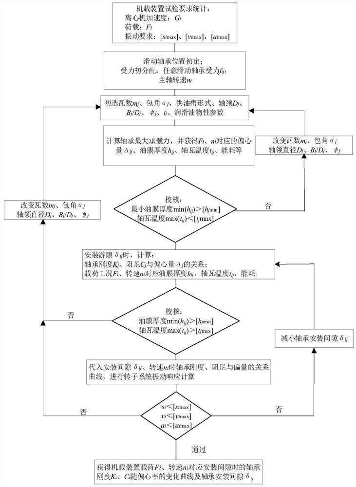
[0060] Such as figure 1 As shown, the method embodiment of the present invention and its implementation process include the following processes:

[0061] The invention optimizes the design of the sliding bearing when the airborne device is installed in the supergravity centrifuge.

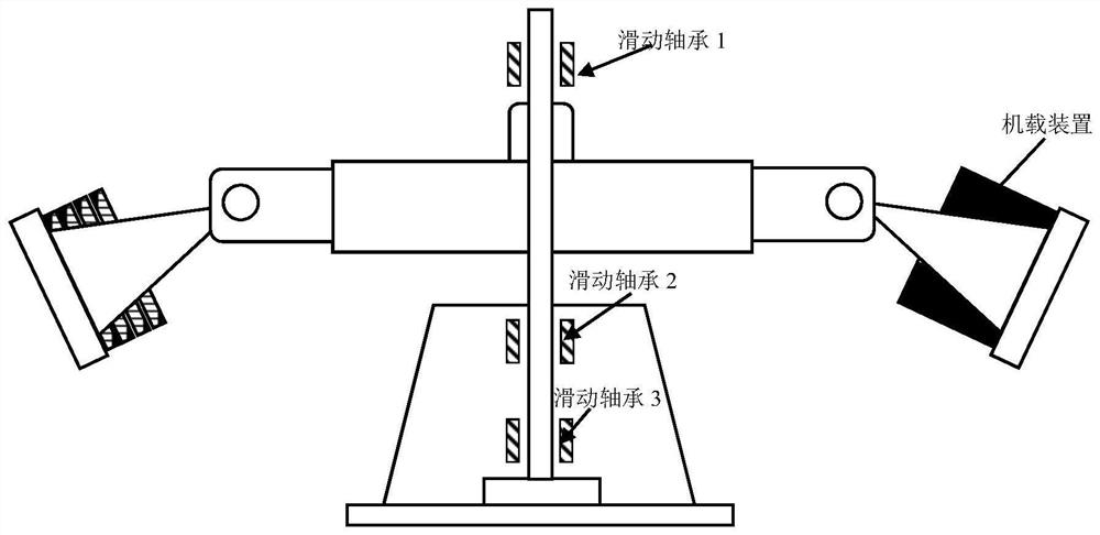
[0062] Such as figure 2 As shown, the airborne device is fixed on the hanging basket of the supergravity centrifuge, and the rotating shaft of the supergravity centrifuge is provided with a guide bearing, which rotates at a high speed under the guide bearing. The guide bearing includes a sliding bearing and a rolling bearing, and the present invention adopts the sliding bearing.

[0063] In a specific implementation, two sliding bearings are arranged at the lower part of the rotating shaft of the supergravity centrifuge, and one sliding bearing is arranged at the...


PUM


Abstract

The invention discloses a method for designing a sliding bearing of a supergravity centrifugal machine based on vibration control. The rigidity and damping characteristics of the bearing are obtained through structural design parameters of a guide bearing of the supergravity centrifugal machine and dynamic characteristic coefficients of the bearing under a certain installation gap, the vibration characteristics in a hanging basket of the supergravity centrifugal machine are obtained through rotor dynamics simulation calculation, the vibration characteristics are compared with vibration requirements of an airborne device and further optimized, finally, structural parameters are kept unchanged in the using process of the sliding bearing, and the centrifugal simulation test of an onboard device is safe and effective by adjusting the installation gap. The problem that vibration control is passive when an existing supergravity centrifugal machine adopts a rolling bearing is solved, a thought is provided for design and use of the sliding bearing for the supergravity centrifugal machine or similar machinery, and certain guiding significance and practical value are achieved for improving the vibration level of a rotating shaft system.

Description

technical field [0001] The invention belongs to a design method of a sliding bearing in the technical field of design and operation of a supergravity centrifuge, and relates to a method for controlling and optimizing the operation quality of a supergravity centrifuge based on the design and use of the sliding bearing, so as to effectively control the vibration control of the supergravity centrifuge. Background technique [0002] The supergravity centrifuge has been widely used in scientific research because of its effects of time reduction, scale reduction and time reduction. Many far-reaching scientific breakthroughs and significant economic design benefits have been achieved in the fields of deep and deep sea resource development, underground space utilization, new material development, geological process research, aerospace and other fields. The development trend of ultra-gravity centrifuges at home and abroad is: large capacity, high centrifugal acceleration, many types ...

Claims


Application Information

Patent Timeline
Patent Type & Authority Applications(China)
IPC IPC(8): B04B9/12
CPCB04B9/12Y02T90/00
Inventor 汪玉冰邱冰静郑建靖凌道盛谢海波赵宇蒋建群陈云敏
Owner ZHEJIANG UNIV
Why Eureka
Try Eureka