
Iron mold sand-lined casting process with core making function and sand-lined mold

A sand-covered iron mold and iron mold technology, which is applied in the manufacture of tools, casting molding equipment, casting molds, etc., can solve the problems of cumbersome procedures and low production efficiency, achieve simplified procedures, low energy consumption costs, and improve overall work efficiency Effect

Pending Publication Date: 2021-07-23
GUANGXI YUCHAI MACHINE PARTS MFG CO LTD
View PDF0 Cites 0 Cited by
  • Summary
  • Abstract
  • Description
  • Claims
  • Application Information

AI Technical Summary

Problems solved by technology

The traditional sand-coating process of iron molds only prepares the outer mold. For the sand core, it needs to be prepared with the help of a hot box or a cold box. The core box tooling must also be manufactured, and the production schedule must be separately arranged for the shape and sand core preparation at the same time. The process is cumbersome and the production efficiency is low.

Method used


Image

  • Iron mold sand-lined casting process with core making function and sand-lined mold
  • Iron mold sand-lined casting process with core making function and sand-lined mold
  • Iron mold sand-lined casting process with core making function and sand-lined mold

Examples


Embodiment 1

[0037] Example 1: SN1000 crankshaft

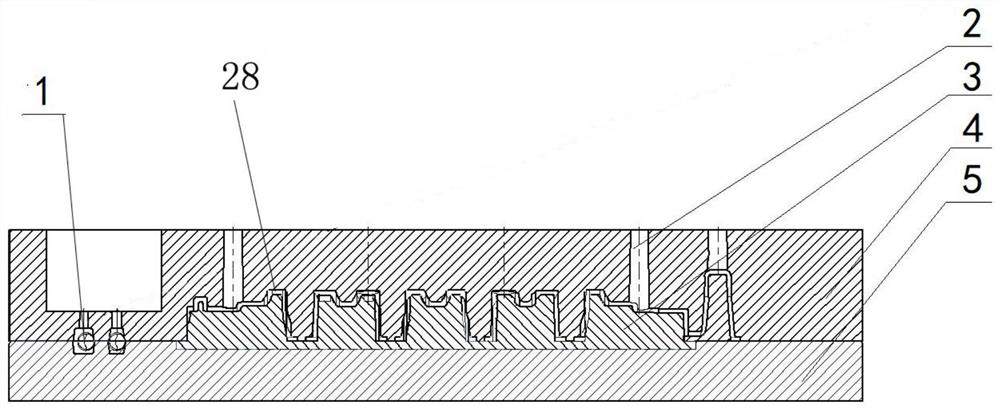
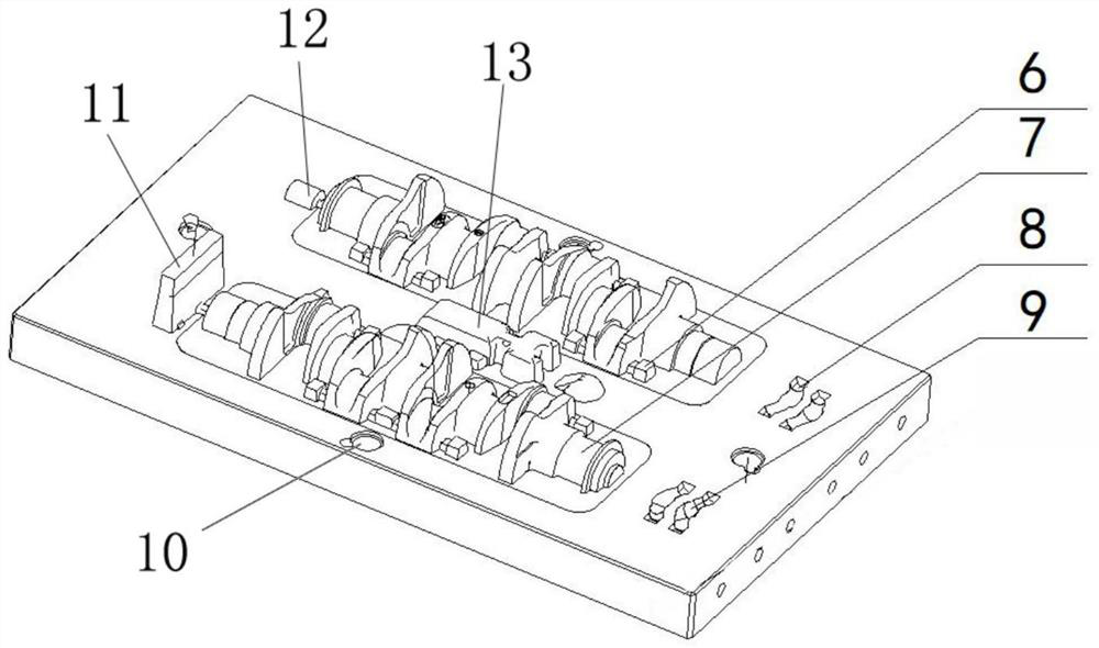
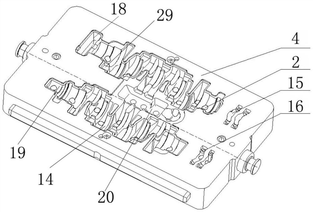
[0038] The weight of the parts is 40Kg, and there are two pieces in a box. Each piece needs to be installed with 4 oil channel sand cores at the position of the connecting rod neck. The sand cores are taken out 4 in the upper shape mold and the upper iron mold, and 4 are taken out in the lower shape mold and the lower iron mold. There is no need to use a core box, and it is directly made from the shape mold and iron mold. The sand core is ejected on the transport trolley, and after the perforation on the cavity of the residual iron sand core is manually removed, glue is glued to the position of the core head, and the shape mold core is completed. It saves a core shooting operator and a core box investment, and the effect is good.

Embodiment 2

[0039] Embodiment 2: Production of EA188 flywheel

[0040] The weight of the parts is 90Kg, one piece per box. The center hole of the flywheel is large in the middle and small at the two ends, so it cannot be lifted out by the lifting core scheme, and only sand cores can be installed. In order to avoid the input of core boxes, a combination of shape molds and iron molds is also used to obtain sand cores while producing shape molds.

[0041] The casting method of the present invention also produces parts such as the differential case of the truck, the crankshaft of the hollow oil passage, and the crankshaft of the six-cylinder engine, all of which realize the coreless box scheme, reduce the cost of tooling and molds, and reduce labor, and have achieved many advantages. significant benefits.


PUM


Abstract

The invention provides an iron mold sand-lined casting process with a core making function and a sand-lined mold. A shape mold comprises a mold bottom plate, the mold bottom plate comprises casting male molds, shape mold sand core head seats and shape mold sand core cavities, the two sides of the casting male molds are connected with the shape mold sand core head seats correspondingly, and shape mold sand core core-head cavities are formed in the two ends of the shape mold sand core cavities are respectively; an iron mold comprises a casting mold cavity, iron mold sand core mold cavities and iron mold sand core head seat mold cavities, iron mold sand core head mold cavities are formed in the two ends of the iron mold sand core mold cavities correspondingly, perforation holes are formed in the casting mold cavity and the iron mold sand core mold cavities correspondingly, a shape mold and the iron mold are in butt joint, so that precoated sand cavities are formed between the casting male molds and the casting mold cavity, and sand core cavities are formed between the shape mold sand core cavities and the iron mold sand core mold cavities. The iron mold precoated sand shape mold cavity and a sand core can be prepared at the same time, a core box manufacturing procedure is omitted, the mold cost is low, and the production efficiency is high.

Description

technical field [0001] The invention belongs to the technical field of casting, and in particular relates to an iron mold sand-coated casting process with a core-making function and a sand-coated mold thereof. Background technique [0002] The molding process of the sand-coated iron mold process requires heating the iron mold and the mold to reach the curing temperature of the coated sand, so as to obtain a mold with a certain thickness of the coated sand layer. The traditional sand-coating process of iron molds only prepares the outer mold. For the sand core, it needs to be prepared with the help of a hot box or a cold box. The core box tooling must also be manufactured, and the production scheduling must be separately arranged for the shape and sand core preparation at the same time. The process is cumbersome and the production efficiency is low. Contents of the invention [0003] In order to solve the above-mentioned technical problems, the present invention provides a...

Claims


Application Information

Patent Timeline
IPC IPC(8): B22C9/06B22C9/10
CPCB22C9/068B22C9/10
Inventor 崔炜陶前昭宋民覃丹枫李异龙李超进
Owner GUANGXI YUCHAI MACHINE PARTS MFG CO LTD
Features
  • Generate Ideas
  • Intellectual Property
  • Life Sciences
  • Materials
  • Tech Scout
  • Unparalleled Data Quality
  • Higher Quality Content
  • 60% Fewer Hallucinations
Learn More