Split type floating fan base and floating fan

A split-type, fan technology, applied in the direction of the hull, transportation and packaging, floating buildings, etc., can solve the problems of large swinging influence, unbearable vertical deformation, etc., and achieve the effect of ensuring economy and good stability

Pending Publication Date: 2021-07-23
HARBIN INST OF TECH SHENZHEN GRADUATE SCHOOL
View PDF0 Cites 1 Cited by
  • Summary
  • Abstract
  • Description
  • Claims
  • Application Information

AI Technical Summary

Problems solved by technology

On the other hand, the drilling and oil riser of the offshore platform cannot withstand large vertical deformation, so it is very important to suppress the heave motion, and the swing has little impact on the safe operation of the platform; The hydrodynamic requirements of the base platform are exactly the opposite. The heave motion has little effect on the energy harvesting of the wind turbine, but the swing has a great influence. Only by keeping the dynamic response of the pitch and roll degrees of freedom small enough can the efficient operation of the wind turbine be guaranteed.

Method used


Image

  • Split type floating fan base and floating fan
  • Split type floating fan base and floating fan
  • Split type floating fan base and floating fan

Examples


Embodiment 1

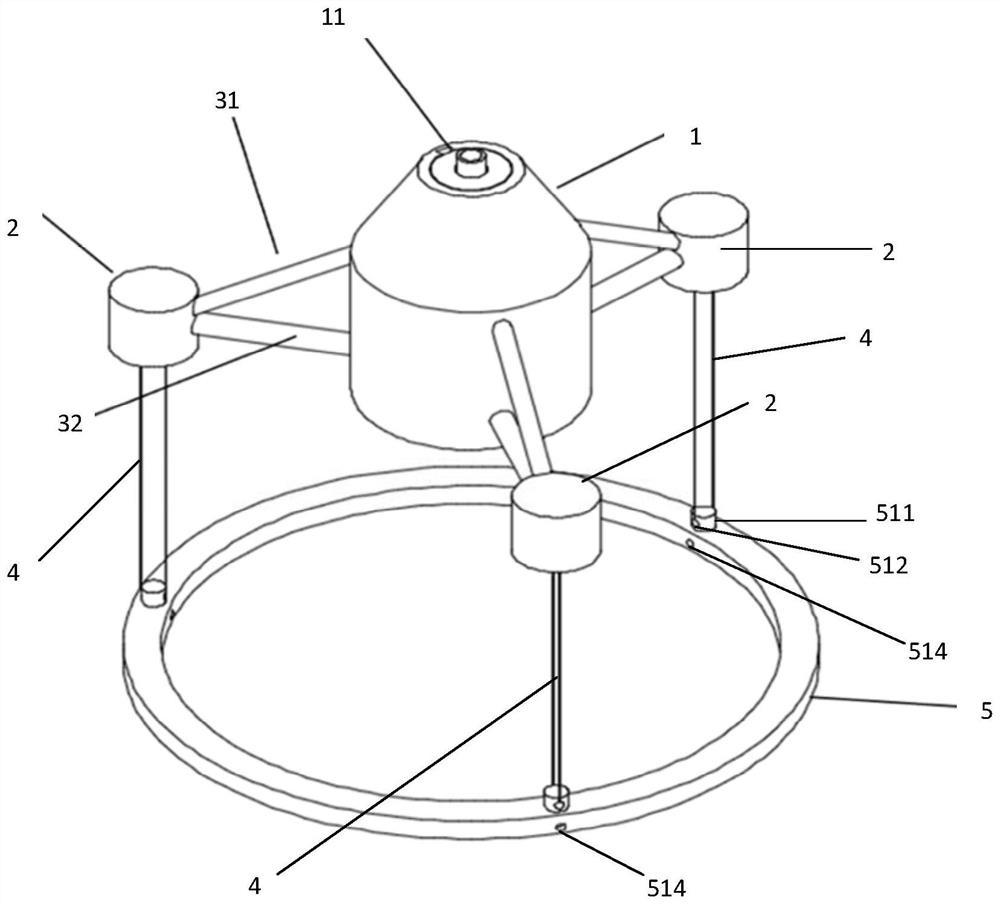
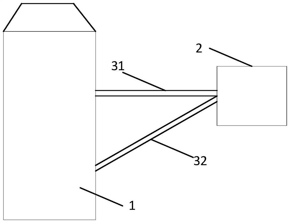
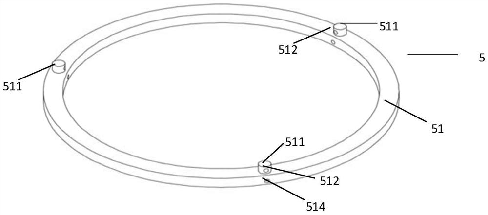
[0044] Embodiment 1 of the present invention discloses a split-type floating fan base, such as figure 1As shown, it includes: a first buoy 1, a plurality of second buoys 2, a connecting rod 3, a plurality of suspension cables 4, and a counterweight 5; wherein, the counterweight 5 includes a counterweight sub-component 51 or a plurality of The counterweight sub-component 51; the detachable connection between the counterweight sub-components 51; the volume of the first buoy 1 is larger than the volume of the second buoy 2; the first buoy 1 is provided with a connecting assembly for connecting a fan Each of the second buoys 2 is connected to the first buoy 1 through the connecting rod 3; a plurality of the second buoys 2 are equally spaced and distributed rotationally symmetrically, and the first buoys 1 are located in a plurality of the buoys. The center position of the second buoy 2 ; each of the second buoys 2 and the counterweight 5 are connected by the suspension cables 4 . ...

Embodiment 2

[0064] Embodiment 2 of the present invention also discloses a floating fan, including the split-type floating fan base described in Embodiment 1. Specifically, Embodiment 2 of the present invention also discloses other related technical features. For specific content of other related technical features, please refer to the description in Embodiment 1. For the purpose of brevity, details are not repeated here.

[0065] The embodiment of the present invention discloses a split-type floating fan base and floating fan, including: a first buoy 1, a plurality of second buoys 2, a connecting rod 3, a plurality of suspension cables 4, and a counterweight 5; wherein, the The counterweight 5 includes a counterweight sub-component 51 or a plurality of counterweight sub-components 51; the counterweight sub-components 51 are detachably connected; the volume of the first buoy 1 is greater than the volume of the second buoy 2 The first buoy 1 is provided with a connection assembly for connec...


PUM


Abstract

The invention provides a split type floating fan base and a floating fan. The split type floating fan base comprises a first buoy, a plurality of second buoys, a connecting rod, a plurality of suspension cables and a balance weight part. The volume of the first buoy is greater than that of the second buoy; the first buoy is provided with a connecting assembly used for being connected with a draught fan. The second buoys are connected with the first buoy through connecting rods; the plurality of second buoys are distributed at equal intervals and are rotationally and symmetrically distributed, and the first buoy is located at the central position of the plurality of second buoys; and each second buoy is connected with the counter weight through a suspension cable. According to the split type floating fan base, on the basis of the configuration of the large first buoy and the multiple small second buoys and the structure that the bottoms of the multiple second buoys are connected with the balance weight pieces, the effect that the waterline area is small but large restoring torque can be provided is achieved, the whole split type floating fan base has excellent stability, small enough pitching and rolling freedom degree dynamic response can be kept, and arrangement of the floating fan is facilitated.

Description

technical field [0001] The invention relates to the structural field of fan bases, in particular to a split-type floating fan base and the floating fan. Background technique [0002] Today, energy and environmental crises are becoming increasingly severe. Human beings urgently need to increase the development of clean and renewable energy to achieve the requirements of sustainable development. With the maturity of wind power technology and the continuous decline of costs, wind power generation has become one of the most widely used new energy power generation methods. And studies have shown that the wind energy that can be developed and utilized in my country's offshore is about 750 million kw, which is three times that of onshore wind energy, and the offshore wind energy reserves are more abundant. Therefore, marine wind energy will be one of my country's important new energy sources. At the same time, the southeast coastal area with the most abundant offshore wind energy...

Claims


Application Information

Patent Timeline
Patent Type & Authority Applications(China)
IPC IPC(8): B63B35/44B63B1/12B63B39/00
CPCB63B1/125B63B35/44B63B39/00B63B2001/126B63B2035/446
Inventor 李朝郑晫文汪爱婷严心如肖仪清
Owner HARBIN INST OF TECH SHENZHEN GRADUATE SCHOOL
Why Eureka
Try Eureka