Drainage device based on highway engineering

A technology for drainage devices and roads, which is applied in the direction of water supply devices, drainage structures, grease/oily substances/floating matter removal devices, etc. It can solve the problems of poor drainage of roads, shortened life of roads, and single functions, etc., to achieve effective road drainage, The effect of reducing the waste of resources

Active Publication Date: 2021-07-23
江苏博业环境科技有限公司
View PDF5 Cites 0 Cited by
  • Summary
  • Abstract
  • Description
  • Claims
  • Application Information

AI Technical Summary

Problems solved by technology

[0002] Highway drainage refers to a complete and unimpeded drainage system formed by a series of facilities for intercepting, draining or removing surface water and groundwater that endanger the road, combined with reasonable planning and design of the conditions along the road. When it is large, it is easy to cause blockage, which will lead to poor drainage of the road, especially for the water-logged parts, it is difficult to effectively drain the water. If the road surface and foundation are soaked in the water for a long time, the life of the road will be shortened. , we propose a drainage device based on highway engineering

Method used


Image

  • Drainage device based on highway engineering
  • Drainage device based on highway engineering
  • Drainage device based on highway engineering

Examples


Embodiment 1

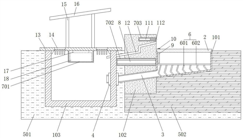
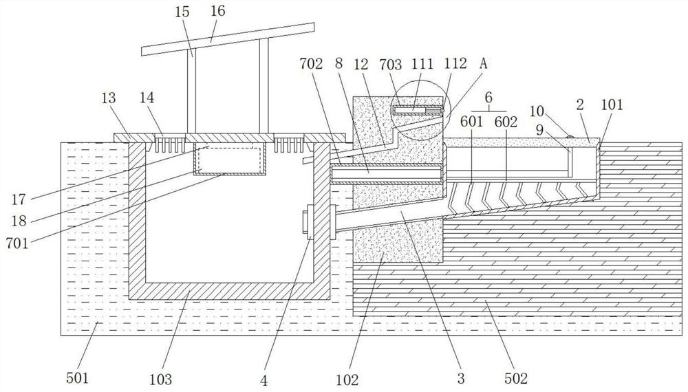
[0029] When the drainage device of this highway project is in use, the intercepting device 6 is set in the drainage groove 101, wherein the center position of each bent filter plate 602 corner on the intercepting device 6 is consistent with the center position of the drain pipe 3, and the curved The folded filter plate 602 is scaled down successively from left to right. By setting the intercepting device 6 with the bent filter plate 602 on the inner wall of the drain tank 101, the stones falling into the drain tank 101 can be effectively intercepted, thereby reducing When the stones move with the water flow, they will wear the inner wall of the drainage tank 101, thereby improving the service life of the drainage tank 101;

[0030] Wherein, the inclined bottom wall of the drain groove 101 and the bottom wall of the drain pipe 3 are located on the same inclined plane, and the angle between the bottom wall of the drain groove 101 and the horizontal plane is 15°-35°, so that the w...

Embodiment 2

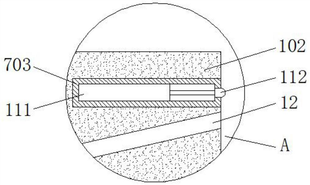
[0034]When pouring the curb stone 102 of the integrated pouring molding structure, the installation channels of the third sealed cavity 703, the overflow pipe 12, the second sealed cavity 702 and the drain pipe 3 are reserved in sequence from top to bottom, and the second The fixed electric telescopic rod 8 is installed in the sealed cavity 702, and the fixed water level sensor 111 is installed in the third sealed cavity 703, which not only improves the intelligence for subsequent use, but also greatly facilitates the subsequent assembly and construction of the drainage device for this highway project ;

[0035] The canal cover plate 13 of the canal 103 is installed and fixed with the solar panel 16 through the bracket 15, the bottom of the canal cover plate 13 is provided with a first sealed cavity 701, and the inside of the first sealed cavity 701 is provided with a controller 17 and a storage battery pack 18, and The controller 17 is electrically connected to the solar pane...


PUM


Abstract

The invention relates to the technical field of drainage of highway engineering, and especially relates to a drainage device based on highway engineering. The device comprises a drainage tank, a curbstone, a canal, a soil base layer and a highway main body, a drainage tank cover plate covers the upper part of the drainage tank, and a drainage pipe at the lower part of the drainage tank is communicated with the interior of the canal through a sealing element; and an annular rainwater grate and a solar panel are arranged on a canal cover plate covering the upper portion of the canal, an overflow pipe is communicated with the interior of the curbstone, an electric telescopic rod is arranged in a second sealing cavity in the middle of the curbstone, and a push strip is fixedly installed at one end of a telescopic part of the electric telescopic rod through a connecting rod. Accumulated water can be effectively drained by arranging an overflow pipe and a water level sensor, blockage can be reduced, meanwhile, the drainage device conducts conversion power supply through a solar panel, resource waste is reduced, more effective road drainage can be intelligently conducted to reduce the damage to the road caused by long-time soaking in accumulated water.

Description

technical field [0001] The invention relates to the technical field of highway engineering drainage, in particular to a drainage device based on highway engineering. Background technique [0002] Highway drainage refers to a complete and unimpeded drainage system formed by a series of facilities for intercepting, draining or removing surface water and groundwater that endanger the road, combined with reasonable planning and design of the conditions along the road. When it is large, it is easy to cause blockage, which will lead to poor drainage of the road, especially for the water-logged parts, it is difficult to effectively drain the water. If the road surface and foundation are soaked in the water for a long time, the life of the road will be shortened. , we propose a drainage device based on highway engineering. Contents of the invention [0003] The purpose of the present invention is to propose a drainage device based on highway engineering in order to solve the shor...

Claims


Application Information

Patent Timeline
Patent Type & Authority Applications(China)
IPC IPC(8): E01C11/22E03F5/04E03F5/06E03F5/14H02S10/20
CPCE01C11/223E03F5/0401E03F5/14E03F5/06H02S10/20E03F2201/40Y02A10/30Y02E70/30Y02E10/50
Inventor 孙红军
Owner 江苏博业环境科技有限公司
Why Eureka
Try Eureka