Al technical title is built by PatSnap Al team. It summarizes the technical point description of the patent document.
A control system and fully automatic technology, applied in mining equipment, earthwork drilling, tunnels, etc., can solve problems such as low device efficiency, increased engineering construction difficulty, and difficult automatic deviation correction, so as to improve work efficiency and work intensity and service life, and the effect of improving work safety
Pending Publication Date: 2021-07-23
山东凤志管道设备有限公司
View PDF6 Cites 2 Cited by
Summary
Abstract
Description
Claims
Application Information
AI Technical Summary
This helps you quickly interpret patents by identifying the three key elements:
Problems solved by technology
Method used
Benefits of technology
Problems solved by technology
[0002] During the pipeline laying process, it is necessary to dig out the pipeline laying opening under the ground, and then use the tractor to pull the pipeline along the laying opening to complete the laying. The traditional roadheader for the pipeline laying opening mainly consists of a base and a roadheader body. Composition, the base and the body of the roadheader are connected by a hydraulic cylinder. During the excavation process, the hydraulic cylinder is used to push the roadheader to move forward to excavate. Since the stroke of the hydraulic cylinder is limited, every time the roadheader digs a certain distance Finally, manually move the base forward for a certain distance, and then start to excavate repeatedly, resulting in low working efficiency of the device, and the traditional roadheader usually transports the soil in the form of a transmission belt, so the roadheader is mainly integrated, during the excavation process Among them, when the excavation route deviates, it is difficult to automatically correct the deviation due to the long body, which increases the difficulty of engineering construction
Method used
Image
Click on the blue label to locate the original text in one second.
Reading with bidirectional positioning of images and text.
Examples
Embodiment Construction
[0018] The specific implementation manners of the present invention will be further described in detail below in conjunction with the accompanying drawings and embodiments. The following examples are used to illustrate the present invention, but are not intended to limit the scope of the present invention.
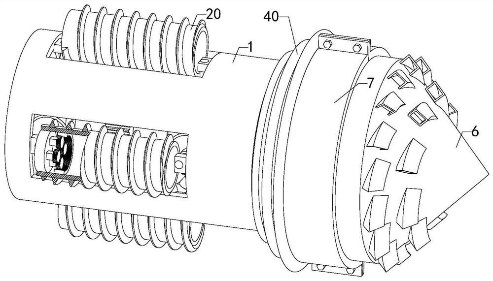
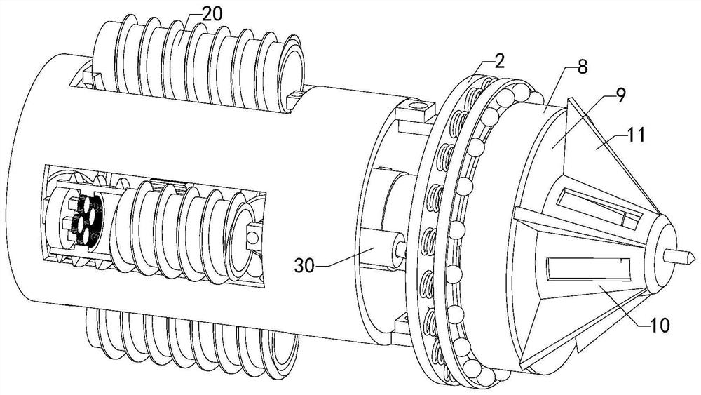
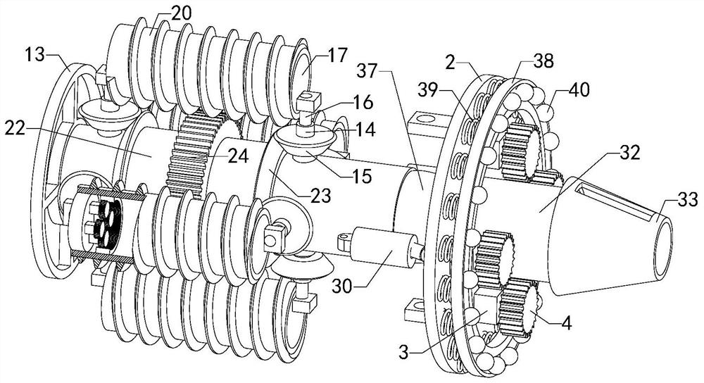
[0019] Such as Figure 1 to Figure 6As shown, a fully automatic control system of a boring machine of the present invention, when it is working, first starts the third motor 25, and under the cooperation of the fourth gear and the third gear 24, the sleeve 22 drives the second The bevel gear 23 rotates, so that the first bevel gear 15 rotates, and under the interaction of the spiral tube 14, the screw rod 16 and the fixed disk 17, multiple groups of walking helical tubes 20 are opened, so that two groups of walking helical tubes 20 contacts with the ground, then start the first motor 3, under the cooperative use of the first gear 4 and the first ring gear 8, the conical c...
PUM
Abstract
The invention relates to the technical field of heading machines, in particular to a full-automatic control system of a heading machine, which can realize automatic deviation correction in the excavating direction, does not influence the conveying of soil, can also enable a device to continuously move while heading, and replaces a traditional operation mode of excavating for a certain distance to move once, so that the working efficiency of the device is improved. The full-automatic control system comprises a main body pipe, a connecting disc, multiple sets of first motors, a first gear, a rotating ring, a conical cutter head, two sets of lantern rings, a first ring gear, a fixing plate, a first frustum cylinder, multiple sets of baffles, a conveying pipe, multiple sets of pipe supporting frames, multiple sets of screw pipes, multiple sets of first bevel gears, screw rods, fixing discs, second motors, second gears, walking spiral pipes, second ring gears, a sleeve, second bevel gears, third gears, four gears and third motors, wherein the connecting disc is connected with the main body pipe through a steering discharging assembly, and the multiple sets of first motors are evenly distributed and mounted on the right end face of the connecting disc.
Description
technical field [0001] The invention relates to the technical field of roadheaders, in particular to a fully automatic control system for roadheaders. Background technique [0002] During the pipeline laying process, it is necessary to dig out the pipeline laying opening under the ground, and then use the tractor to pull the pipeline along the laying opening to complete the laying. The traditional roadheader for the pipeline laying opening mainly consists of a base and a roadheader body. Composition, the base and the body of the roadheader are connected by a hydraulic cylinder. During the excavation process, the hydraulic cylinder is used to push the roadheader to move forward to excavate. Since the stroke of the hydraulic cylinder is limited, every time the roadheader digs a certain distance Finally, manually move the base forward for a certain distance, and then start to excavate repeatedly, resulting in low working efficiency of the device, and the traditional roadheader ...
Claims
Application Information
Patent Timeline
Application Date:The date an application was filed.
Publication Date:The date a patent or application was officially published.
First Publication Date:The earliest publication date of a patent with the same application number.
Issue Date:Publication date of the patent grant document.
PCT Entry Date:The Entry date of PCT National Phase.
Estimated Expiry Date:The statutory expiry date of a patent right according to the Patent Law, and it is the longest term of protection that the patent right can achieve without the termination of the patent right due to other reasons(Term extension factor has been taken into account ).
Invalid Date:Actual expiry date is based on effective date or publication date of legal transaction data of invalid patent.