Steam turbine lubricating oil high-level oil tank system

A high-level fuel tank and lubricating oil technology, which is applied in mechanical equipment, engine components, machines/engines, etc., can solve problems such as restricting the application of high-level fuel tanks and operating risks of the unit, so as to achieve short effective fuel supply time, large fuel supply, and reduced fuel consumption. The effect of volume

Active Publication Date: 2021-07-23
DONGFANG TURBINE CO LTD
View PDF7 Cites 3 Cited by
  • Summary
  • Abstract
  • Description
  • Claims
  • Application Information

AI Technical Summary

Problems solved by technology

[0005] The insufficiency of the original high-level fuel tank system restricts the application of high-level fuel tanks on large units, which brings certain risks to the operation of the unit

Method used


Image

  • Steam turbine lubricating oil high-level oil tank system

Examples


Embodiment 1

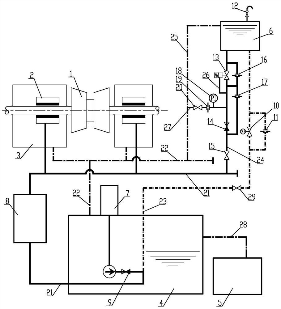
[0027] Such as figure 1 As shown, in this embodiment, a steam turbine lubricating oil high-level oil tank system includes a main oil tank 4, an oil pump 7, an oil supply pipeline 21, a bearing housing 3 and an oil return pipeline 22 connected sequentially in accordance with the flow sequence of lubricating oil, and the oil supply The pipeline 21 is connected with an oil cooler 8, the oil supply pipeline 21 is connected with an oil filling pipeline 23, the oil filling pipeline 23 is connected with a high-level oil tank 6, and a high-level oil supply line is connected between the high-level oil tank 6 and the bearing housing 3 Line 24.

[0028] The unit is in the working condition before starting, the oil pump 7 is running, the lubricating oil passes through the oil pump check valve 9 behind the oil pump 7, and one way passes through the oil supply pipeline 21 and the oil cooler 8 to supply oil to the bearing 2; the other way passes through the oil filling pipeline 23 Fill the ...

Embodiment 2

[0032] On the basis of the above embodiments, in this embodiment, the oil filling pipeline 23 is provided with an A isolation valve 29 and an electric oil filling valve 10 in sequence according to the flow direction of lubricating oil; the electric oil filling valve 10 is connected in parallel with an oil temperature hole plate 11. The electric oil filling valve 10 can control the communication or closing of the oil filling pipeline 23, so as to open when oil filling is required and close after filling.

Embodiment 3

[0034] On the basis of the above embodiments, in this embodiment, the high-level oil supply pipeline 24 is sequentially provided with a self-operated regulating valve 13, an oil discharge check valve 14, and a B isolation valve 15 according to the flow direction of lubricating oil. The pipeline between the self-operated regulating valve 13 and the oil discharge check valve 14 is communicated with a pressure introduction pipe 26 communicated with the self-operated regulating valve 13 .

[0035] In this embodiment, when the unit lubricating oil fails, the oil pump 7 stops, the pressure of the lubricating oil supply pipeline 21 decreases, the oil discharge check valve 14 automatically opens under the pressure difference, and the lubricating oil in the high oil tank 6 passes through The self-operated regulating valve 13 and the oil supply orifice 16 supply oil to the bearing 2. The actuator of the self-operated regulating valve 13 automatically adjusts the opening through the press...


PUM


Abstract

The invention discloses a steam turbine lubricating oil high-level oil tank system. The steam turbine lubricating oil high-level oil tank system comprises a main oil tank, an oil pump, an oil supply pipeline, a bearing box and an oil return pipeline which sequentially communicate with each other according to a lubricating oil circulation sequence, the oil supply pipeline communicates with an oil cooler and communicates with an oil charging pipeline, the oil charging pipeline communicates with a high-level oil tank, and a high-level oil supply pipeline communicates between the high-level oil tank and the bearing box. The steam turbine lubricating oil high-level oil tank system has the beneficial effects that an existing system does not depend on an electrical system, can automatically and stably control the oil supply pressure, only has the requirement for the lowest arrangement height of the oil tank, has no requirement for the structural form, can maintain the oil temperature and the oil level of the high-level oil tank, and has an online testing function. According to the steam turbine lubricating oil high-level oil tank system, the volume of the high-level oil tank can be effectively reduced, the arrangement requirement of the high-level oil tank is lowered, regular tests can be carried out, the safety of a unit lubricating oil system is enhanced, and oil cut-off and bush burning accidents are avoided.

Description

technical field [0001] The invention relates to the technical field of steam turbine lubricating oil, in particular to a high-level oil tank system for steam turbine lubricating oil. Background technique [0002] The steam turbine lubricating oil system is very important in the operation of the unit. If the lubricating oil is cut off, the unit will not be able to supply oil normally. Not only will the unit stop running, but the bearing bush will be burned, the bearing will be worn, and even the serious consequences of fire will occur. Therefore, the unit usually It is necessary to configure a high-level oil tank system to meet the requirements of supplying oil to the bearing when the lubricating oil system fails to achieve a safe shutdown. [0003] The lubricating oil supply pressure of small units is low, and the oil demand is small. The high-level oil tank is directly connected to the lubricating oil supply pipeline through the pipeline, and the system is very simple; The...

Claims


Application Information

Patent Timeline
Patent Type & Authority Applications(China)
IPC IPC(8): F01D25/18F01D25/20F01D25/00
CPCF01D25/18F01D25/20F01D25/00
Inventor 阳欧彭立杜立刚高扬刘经武颜强高晓亮姬艳云刘兴王泽锐
Owner DONGFANG TURBINE CO LTD
Why Eureka
Try Eureka