Capacitive proximity switch sensor

A technology of proximity switches and sensors, applied in the field of sensors, can solve the problems of unfavorable long-term stability of capacitive proximity switches, short detection distances of proximity switches, and inability to achieve long-distance detection, etc. Effect

Active Publication Date: 2021-07-23
SHANGHAI LANBAO SENSING TECH
View PDF25 Cites 1 Cited by
  • Summary
  • Abstract
  • Description
  • Claims
  • Application Information

AI Technical Summary

Problems solved by technology

[0009] b) Affected by parasitic capacitance, since the capacitance of the plate itself is about 10pF, the parasitic capacitance of lines and other devices is relatively large at the pF level. The whole system not only detects the change of plate capacitance, but also the parasitic capacitance Participated in the signal calculation process and adversely affected the detection results
[0010] c) Affected by the filling material, the interior of the proximity switch generally needs to be filled with resin materials. In order to fix the internal circuit board and structural components, it can also achieve IP waterproof performance, but the size and change of the dielectric constant of the filling material is related to the plate capacitance. The long-term creep of the filling material is not conducive to the long-term stability of the capacitive proximity switch
[0011] d) The sensitivity of the existing technical scheme to convert the change of the plate capacitance into the change of the voltage and current signal is low, so the detection distance of the traditional capacitance proximity switch is relatively short, and long-distance detection cannot be realized

Method used


Image

  • Capacitive proximity switch sensor
  • Capacitive proximity switch sensor
  • Capacitive proximity switch sensor

Examples


Embodiment Construction

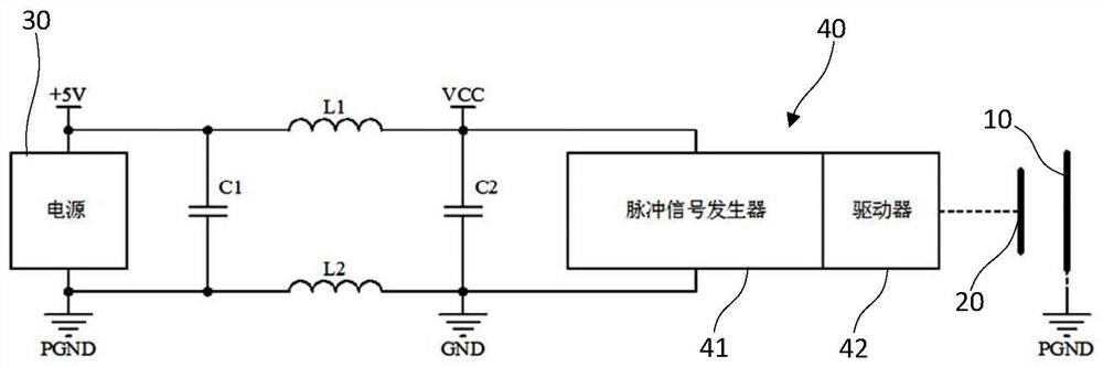
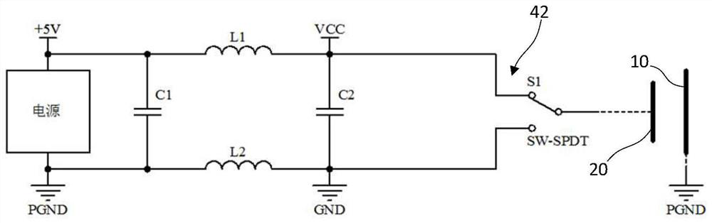
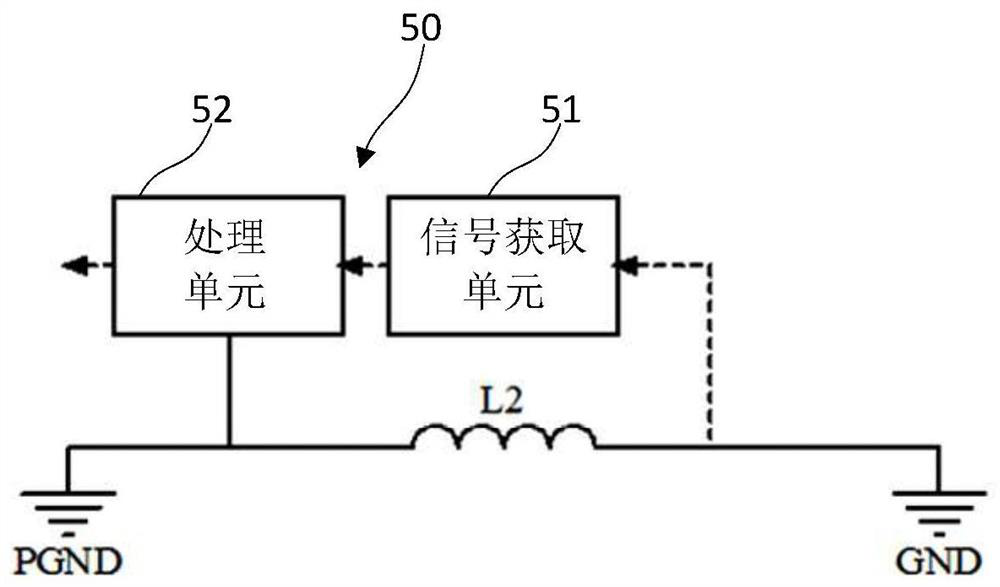
[0048] Such as figure 1 As shown, the embodiment of the present invention provides a capacitive proximity switch sensor for detecting the distance between it and the metal surface to be tested. The metal surface 10 to be tested is electrically connected to the ground terminal PGND, and the two potentials are the same. In this embodiment, the capacitive proximity switch sensor includes: a detection plate 20 , a power supply 30 , a driving module 40 and a signal processing module 50 . specific:

[0049]The detection pole plate 20 is set opposite to the metal surface 10 to be tested, and the two form an external capacitance. The metal surface 10 to be tested can adopt the surface of the metal component of the target, and its area is much larger than the area of ​​the detection pole plate 20, so the effective area of ​​the metal surface 10 to be tested is less affected by temperature, so that only the detection pole plate is included in the external capacitance 20 will be affe...


PUM


Abstract

The invention discloses a capacitive proximity switch sensor, which is used for detecting the distance between the capacitive proximity switch sensor and a detected metal surface, and comprises a detection pole plate, a power supply, a driving module, and a signal processing module. The detection pole plate is arranged opposite to a detected metal surface and forms an external capacitor with the detected metal surface; the anode of the power supply is connected with a power supply end through a first inductor; the cathode is connected with a grounding end, and is connected with a common end through the second inductor; a second capacitor is connected between the power supply end and the grounding end; the first inductor and the second inductor form a differential mode inductor; the cathode of the driving module is connected with the common end, and the anode is connected with the power supply end; the driving module is used for generating a driving signal and coupling the driving signal to the detection pole plate; and the signal processing module is coupled to the two ends of the second inductor and detects the external capacitor by detecting the voltage change at the two ends of the second inductor. Target detection is achieved through the external capacitor composed of the single pole plate and the detected target, the capacitance of the pole plate does not serve as a detection basis, and the capacitance value of the external capacitor is more stable.

Description

technical field [0001] The invention relates to the field of sensors, in particular to a capacitive proximity switch sensor. Background technique [0002] The capacitive proximity switch uses various capacitors as sensing elements, and is a device that converts mechanical quantities into capacitance changes. Capacitive proximity switches, that is, capacitive sensors, can be divided into three types: variable area type, variable pole distance type, and variable medium type. In the traditional capacitive proximity switch detection technology, the built-in double-sided copper-clad PCB board of the sensor is a capacitor as the measured object, and its variation is used as the basis for the sensing distance. [0003] There are mainly three existing technical solutions for the capacitive proximity switch, the change of the oscillation signal generated by the capacitor participating in the oscillator, the change of the charging and discharging time of the capacitor, and the change...

Claims


Application Information

Patent Timeline
Patent Type & Authority Applications(China)
IPC IPC(8): G01B7/14
CPCG01B7/14
Inventor 许永童谢勇吴施庆陈晨姜春华
Owner SHANGHAI LANBAO SENSING TECH
Why Eureka
Try Eureka