Resolution multiplication DMD projection system based on birefringence principle

A projection system, birefringence technology, applied in the field of projection, can solve the problems of increased cost, poor system stability, complex optical path, etc., to achieve the effect of more optimized picture quality, guarantee stability and compactness

Pending Publication Date: 2021-07-23
GENGUAN INTELLIGENT TECH HANGZHOU CO LTD
View PDF1 Cites 1 Cited by
  • Summary
  • Abstract
  • Description
  • Claims
  • Application Information

AI Technical Summary

Problems solved by technology

[0005] In terms of projection, the existing resolution-enhancing solutions use two or more projection devices to splice multiple projection images, which will not only increase the cost, but also make the entire system too bulky due to the complexity of the optical path
And under multiple projections, it is necessary to superimpose different images to achieve super-resolution, that is, precise alignment can ensure the normal image display of the system, so the system is prone to image misalignment due to external interference, which makes the stability of the system very poor

Method used


Image

  • Resolution multiplication DMD projection system based on birefringence principle
  • Resolution multiplication DMD projection system based on birefringence principle
  • Resolution multiplication DMD projection system based on birefringence principle

Examples


Embodiment 1

[0031] Attached below figure 1 A kind of embodiment of the present invention is described in further detail:

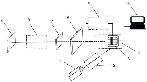
[0032] Such as figure 1 As shown, an implementation of a DMD projection system based on the principle of birefringence for multiplication of resolution, including a laser 1, a laser beam expander and collimator optical path 2, a digital micromirror device DMD 3, a DMD module 4, and a TN liquid crystal module 5. Synchronous control circuit 6, birefringent optical element 7, projection optical path 8, projection screen 9, host computer module 10. The laser beam emitted by the laser 1 passes through the laser beam expansion and collimation optical path 2, and the spot diameter becomes larger, and irradiates evenly on the digital micromirror device DMD3 of the DMD module 4 in a collimated direction; the display pattern of the digital micromirror device DMD3 is controlled by the host Controlled by the computer module 10, the patterns decomposed by the image algorithm of ...

Embodiment 2

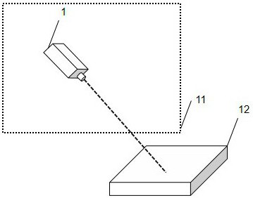
[0034] The present invention can be applied in the field of lithography, combined with the attached figure 1 with attached figure 2 Specific steps are as follows:

[0035] (1) Load the pattern to be photolithographically into the DMD module 4 through the host computer module 10 .

[0036] (2) Turn on the laser 1 and let the projection image irradiate on the photosensitive layer of the substrate 12 after passing through the system 11 of the present invention, so as to realize super-resolution lithography.

Embodiment 3

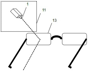
[0038] Attached below figure 1 with attached image 3 A further detailed description of an implementation of the present invention applied to AR glasses:

[0039] Such as image 3 As shown, this system can be integrated and applied in AR glasses. When the laser 1 is turned on, the projected pattern is irradiated on the lens 13 of the AR glasses after passing through the system 11 of the present invention, and then the augmented reality display with the resolution of the near-eye display area multiplied can be realized. .


PUM


Abstract

The invention relates to a resolution multiplication DMD projection system based on a birefringence principle. The system comprises a laser, a laser beam expanding and collimating light path, a DMD module, an upper computer module, a TN liquid crystal module, a synchronous control circuit, a birefringence optical assembly, a projection light path and a projection screen. The laser emits laser to serve as an illumination light source of the projection system, the DMD projection light path projects a reflected laser picture into a subsequent system, an image decomposed by a computer image algorithm is loaded on the DMD through the upper computer control system, and the projected image is staggered and superposed after passing through the liquid crystal control module and the birefringence optical assembly. The system aims to realize projection display with resolution multiplication and improved image quality on the basis of not changing the physical resolution of hardware projection equipment.

Description

technical field [0001] The invention belongs to the technical field of projection, and relates to a DMD projection system based on the principle of double refraction and multiplication of resolution. Background technique [0002] The traditional projection system shows certain limitations in its development. With the progress of the times, 3D display technology is developing rapidly, and technologies such as virtual reality and augmented reality suitable for near-eye display will be applied to more scenarios. In 3D display, giving different image data to the left and right eyes at the same time means that more pixel information needs to be generated. In some technical fields related to optics, the resolution of projection is also important. For example, in the field of lithography, higher mask resolution means that devices with higher precision can be produced. Due to the limitation of the physical resolution of the hardware, the traditional projection system must rely on ...

Claims


Application Information

Patent Timeline
Patent Type & Authority Applications(China)
IPC IPC(8): G03B21/00G03B21/20G02B27/01
CPCG03B21/006G03B21/2033G02B27/0101
Inventor 何赛灵张祎静菲尔苏尔曼
Owner GENGUAN INTELLIGENT TECH HANGZHOU CO LTD
Why Eureka
Try Eureka