Design method for low-shock-wave-loss inwards-concave molded line of zero-prerotation turbine movable vane

A design method and concave technology, applied in the field of aerodynamics, can solve the problems of flow loss and high Mach number, and achieve the effect of reducing shock wave loss, reducing shock wave loss and improving turbine efficiency

Pending Publication Date: 2021-07-23
INST OF ENGINEERING THERMOPHYSICS - CHINESE ACAD OF SCI
View PDF0 Cites 0 Cited by
  • Summary
  • Abstract
  • Description
  • Claims
  • Application Information

AI Technical Summary

Problems solved by technology

Therefore, with the increase of the aerodynamic load, the airflow on the suction surface accelerates sharply on the longer unshielded section, and the Mach number near the trailing edge of the suction surface is higher, resulting in a large amount of flow loss induced by the shock wave at the trailing edge of the suction surface of the blade

Method used


Image

  • Design method for low-shock-wave-loss inwards-concave molded line of zero-prerotation turbine movable vane
  • Design method for low-shock-wave-loss inwards-concave molded line of zero-prerotation turbine movable vane
  • Design method for low-shock-wave-loss inwards-concave molded line of zero-prerotation turbine movable vane

Examples


Embodiment Construction

[0030] In order to make the purpose, technical solutions and advantages of the embodiments of the present invention clearer, the technical solutions in the embodiments of the present invention will be clearly and completely described below in conjunction with the drawings in the embodiments of the present invention. Obviously, the described embodiments It is only some embodiments of the present invention, but not all embodiments. Based on the embodiments of the present invention, all other embodiments obtained by persons of ordinary skill in the art without making creative efforts belong to the protection scope of the present invention.

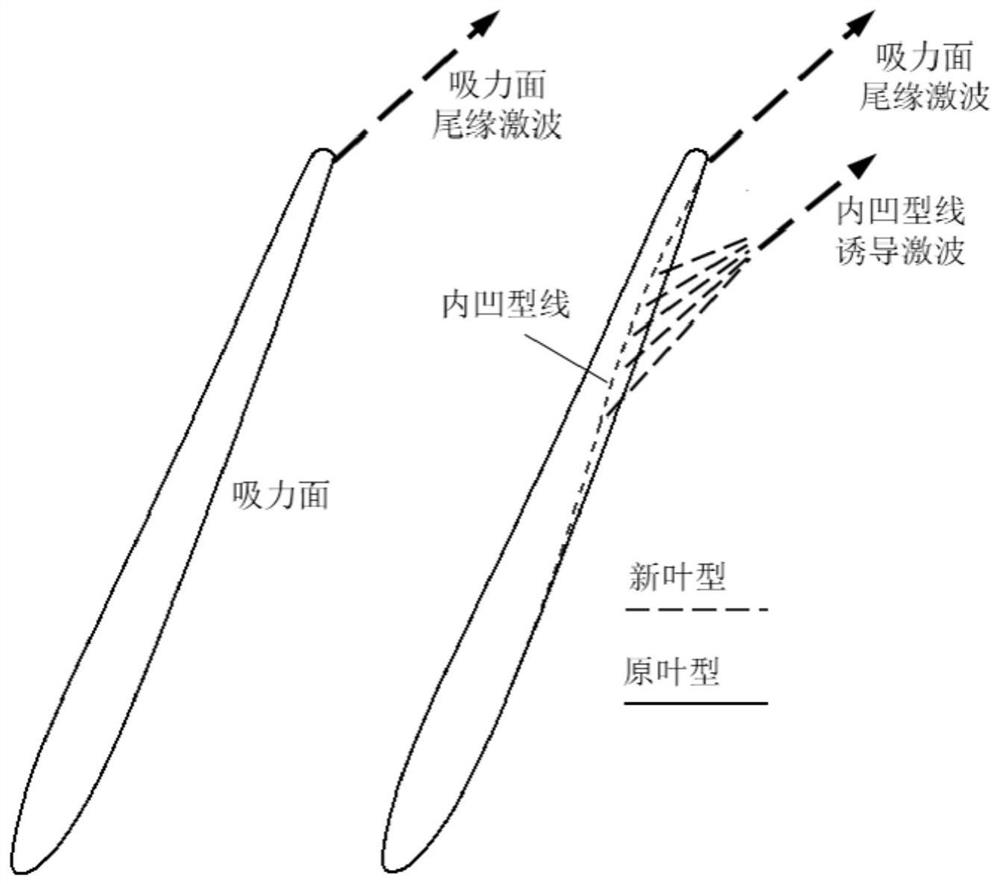
[0031] In order to reduce the shock wave loss, according to the research on shock wave loss in gas dynamics, one shock wave can be decomposed into two shock waves. In order to achieve shock wave decomposition, a concave profile can be designed upstream of the existing shock wave to induce a new shock wave, such as image 3 As shown, accordin...


PUM


Abstract

The invention discloses a design method for an inwards-concave molded line of a non-covering section on a suction surface of a zero-prerotation turbine movable vane. The invention aims to reduce the loss of a high-load zero-prerotation turbine movable vane suction surface trailing edge shock wave and improve turbine efficiency. According to the method, an inwards-concave is designed at the upstream position of an existing suction surface trailing edge shock wave to induce a new shock wave; and according to the zero-prerotation turbine movable vane, the non-covering section of the suction surface is long due to an axial air inlet, the long non-covering section of the suction surface is suitable for arranging the inwards-concave molded line to induce the new shock wave, an outwards-extending shock wave of the tail edge of the suction surface is decomposed into two shock waves, and shock wave loss is reduced.

Description

technical field [0001] The invention relates to the field of aerodynamics, and relates to a method for designing a profile of a turbine blade, in particular to a method for designing a concave profile with low shock loss for a zero-pre-rotation turbine blade. Background technique [0002] The zero pre-rotation turbine blade is a rotor blade that works on the first stage of the turbine. The upstream guide vane is removed, which is beneficial to shorten the axial length of the aero-engine, reduce the aerodynamic loss and cooling air consumption related to the guide vane, and improve the thrust-to-weight ratio of the aero-engine. [0003] Such as figure 1 As shown, since there is no pre-swirl provided by the upstream guide vane, the airflow from the outlet of the combustion chamber directly enters the turbine bucket along the axial direction, so it is called "zero-pre-swirl turbine bucket". On the one hand, the axial air intake leads to little room for blade turning (less than...

Claims


Application Information

Patent Timeline
Patent Type & Authority Applications(China)
IPC IPC(8): G06F30/20G06F30/17G06F119/14
CPCG06F30/17G06F30/20G06F2119/14
Inventor 赵巍赵庆军隋秀明胡斌雒伟伟项效镕
Owner INST OF ENGINEERING THERMOPHYSICS - CHINESE ACAD OF SCI
Why Eureka
Try Eureka