Trans/supersonic compressor rotor blades with shock control bulbs

A compressor rotor, supersonic technology, applied in the direction of machines/engines, mechanical equipment, liquid fuel engines, etc., to achieve the effect of improving the stable working range, improving performance, and reducing shock wave intensity

Active Publication Date: 2021-02-12
DALIAN MARITIME UNIVERSITY
View PDF4 Cites 0 Cited by
  • Summary
  • Abstract
  • Description
  • Claims
  • Application Information

AI Technical Summary

Problems solved by technology

At present, this shock wave control technology is mainly used in the airfoil with outflow to control the wave resistance, and there are also some applications in the supersonic inlet with inflow, but there are few applications in the field of turbomachinery with inflow, especially in transversal airfoils. / Applied research in supersonic compressors has just started

Method used


Image

  • Trans/supersonic compressor rotor blades with shock control bulbs
  • Trans/supersonic compressor rotor blades with shock control bulbs
  • Trans/supersonic compressor rotor blades with shock control bulbs

Examples


Embodiment 1

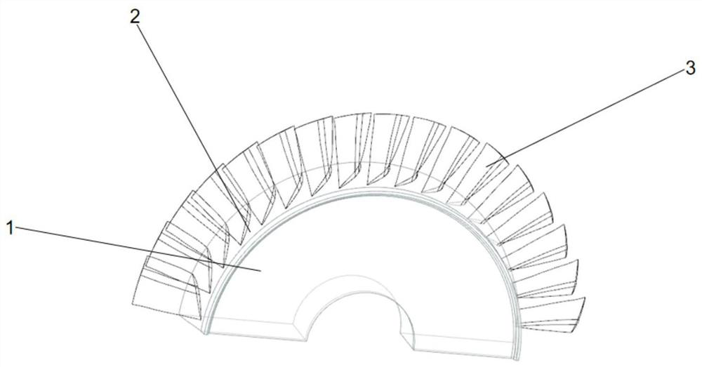
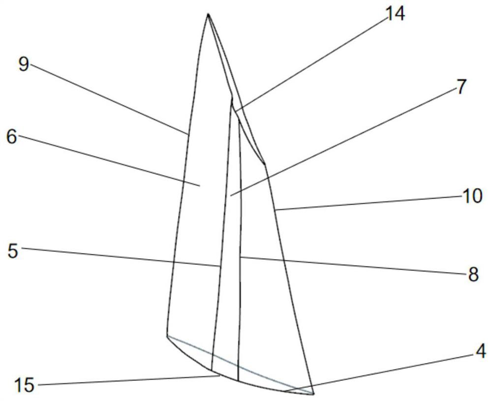
[0077] like Figure 1-5 As shown, the trans / supersonic compressor rotor with continuous shock control bulge provided by the present invention is the trans / supersonic compressor rotor with continuous full-blade height shock control bulge and the continuous partial-blade height shock control Bulky trans / supersonic compressor rotor.

[0078]The trans / supersonic compressor rotor with continuous full-blade high-shock control bulge includes disc 1 and trans / supersonic compressor rotor blade 3 with continuous full-blade high-shock control bulge, and disc 1 is with continuous full-blade The base of the trans / supersonic compressor rotor blade 3 with high shock wave control bulging, the outer edge of the wheel disc 1 is provided with a hub 2, and a plurality of trans / supersonic compressor rotor blades 3 with continuous full-blade hyper shock control bulging along the hub 2 The circumferential intervals are set in sequence.

[0079] The trans / supersonic compressor rotor with continuous...

Embodiment 2

[0084] Different from Embodiment 1, the shock wave control bulge in this embodiment is discontinuously distributed in the blade height direction of the suction surface of the trans / supersonic compressor blade.

[0085] like Figure 6-9 As shown, the trans / supersonic compressor rotor with discontinuous shock wave control bulge provided by the present invention is respectively the trans / supersonic compressor rotor with discontinuous full-blade high shock wave control bulge and the discontinuous part Leaf height shock control for bulging trans / supersonic compressor rotors.

[0086] The trans / supersonic compressor rotor with discontinuous full-blade high-shock control bulge includes a disc 1 and the trans / supersonic compressor rotor blade 16 with discontinuous full-blade high-shock control bulge. Disc 1 is the base of a trans / supersonic compressor rotor blade 16 with discontinuous full-blade hyper-shock wave control bulges. The outer edge of disc 1 is provided with hub 2, and mul...


PUM


Abstract

The invention provides a trans / supersonic compressor rotor blade with a shock wave control bulge, including a blade root, a blade top, a pressure surface, and a suction surface; a shock wave control bulge is provided on the suction surface, and the shock wave control bulge includes continuity Shock wave control bulge and discontinuous shock wave control bulge; continuous shock wave control bulge distributes continuously along the blade height direction; discontinuous shock wave control bulge discontinuously distributes along blade height direction; continuous shock wave control bulge includes continuous Shock-wave-controlled bulge of the whole leaf height and continuous part-height shock-wave-controlled bulge; discontinuous shock-wave-controlled bulge includes shock wave control bulge of discontinuous whole leaf height and shock wave control bulge of discontinuous part of leaf height. The invention only needs to slightly change the suction surface of the blade locally, and can improve the shock wave system structure inside the trans / supersonic compressor without changing the flow rate, and improve the performance of the trans / supersonic compressor, and has simple structure and design Flexibility, lower cost and other advantages.

Description

technical field [0001] The invention relates to a trans / supersonic compressor rotor blade with a shock wave control bulb. Background technique [0002] Gas turbines have been widely used as power devices in the fields of aerospace and ships since they were put into practical use in 1939. In order to further improve the thrust-to-weight ratio / power-to-weight ratio of the gas turbine and reduce fuel consumption, the compressor, one of the three core components of the gas turbine, needs to continuously improve the boost ratio and efficiency. The improvement of the pressure ratio and efficiency of the compressor mainly depends on the deepening of people's understanding of its internal flow characteristics and the development and application of various flow control technologies. [0003] For trans / supersonic compressors, the shock loss and the shock-induced boundary layer separation loss are one of the main sources of flow loss. Therefore, in order to improve the performance of...

Claims


Application Information

Patent Timeline
Patent Type & Authority Patents(China)
IPC IPC(8): F04D29/38F04D29/66F04D29/68
CPCF04D29/384F04D29/388F04D29/666F04D29/681F05D2240/306
Inventor 韩吉昂钱薪伟胡义丁小娟
Owner DALIAN MARITIME UNIVERSITY
Why Eureka
Try Eureka