
Method for identifying modal parameters of oscillation signals

A technology of modal parameters and oscillating signals, which is applied to pattern recognition in signals, character and pattern recognition, instruments, etc., can solve problems such as slow calculation speed, large influence by noise, and uncertain order determination, and achieve the goal of overcoming noise Sensitivity, high-frequency noise elimination effect

Active Publication Date: 2021-07-23
FUDAN UNIV
View PDF20 Cites 1 Cited by
  • Summary
  • Abstract
  • Description
  • Claims
  • Application Information

AI Technical Summary

Problems solved by technology

The Kalman filtering method can eliminate the influence of noise and has good adaptability to different input signals, but the calculation accuracy and convergence speed are greatly affected by the initial parameter settings.
The matrix beam identification method can accurately estimate the oscillation mode of the system and has strong anti-noise ability, but if the signal has time-varying characteristics, the calculation error of the algorithm is large, and the dynamic characteristics of the oscillation cannot be revealed
The Prony method can extract information such as oscillation signal mode, phase angle, and damping, but there are problems such as being greatly affected by noise, slow calculation speed, and uncertain order problems.
The HHT algorithm is a new type of analysis method developed in recent years that is suitable for non-stationary and nonlinear signals. The traditional HHT algorithm is affected by the endpoint effect. Although the instantaneous frequency, instantaneous amplitude and attenuation factor of the oscillation mode can be obtained, It is difficult to achieve high calculation accuracy

Method used


Image

  • Method for identifying modal parameters of oscillation signals
  • Method for identifying modal parameters of oscillation signals
  • Method for identifying modal parameters of oscillation signals

Examples


Embodiment

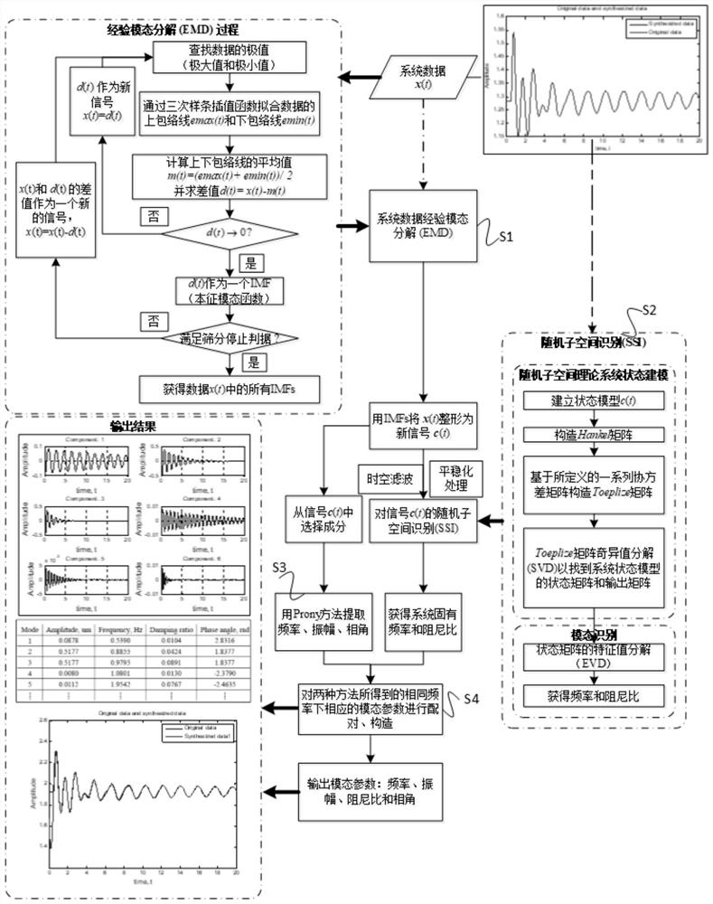
[0100] A method for identifying the modal parameters of an oscillating signal, such as figure 1 shown, including the following steps:

[0101] S1: Obtain the original signal of the system, process the original signal through the empirical mode decomposition method, and obtain a new signal.

[0102] In this embodiment, the acquired original signal is a group of low-frequency oscillation sampling signals, the sampling frequency is 100 Hz, the sampling time is 0-20 s, and there are 2000 sampling points in total.

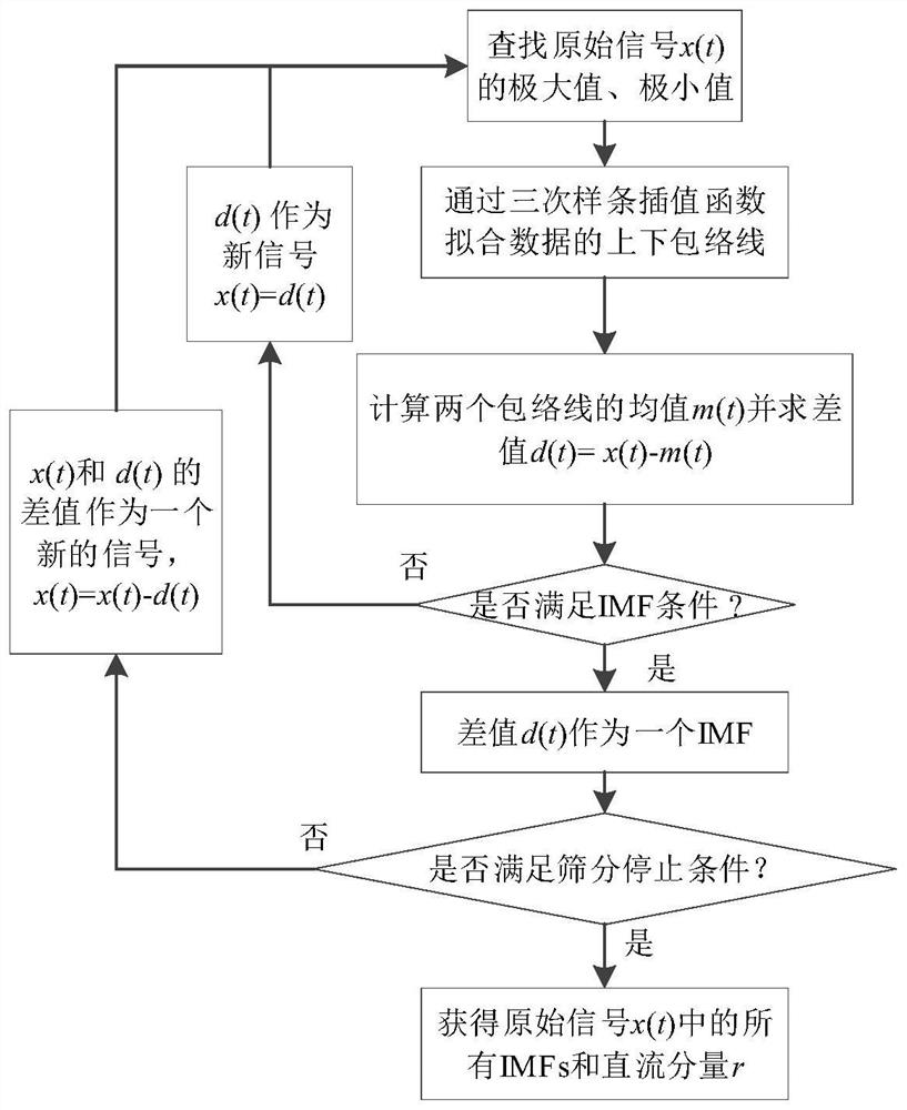
[0103] Such as figure 2 As shown, step S1 specifically includes:

[0104] S11: Deriving the original signal x(t) of the system, and extracting the extreme value of x(t);

[0105] S12: Fit the upper and lower envelopes of x(t), and obtain the maximum value e of the envelope max (t) and the minimum e mim (t);

[0106] In this embodiment, a cubic spline interpolation function is used to fit the upper envelope and the lower envelope.

[0107] S13: Calculate the enve...


PUM


Abstract

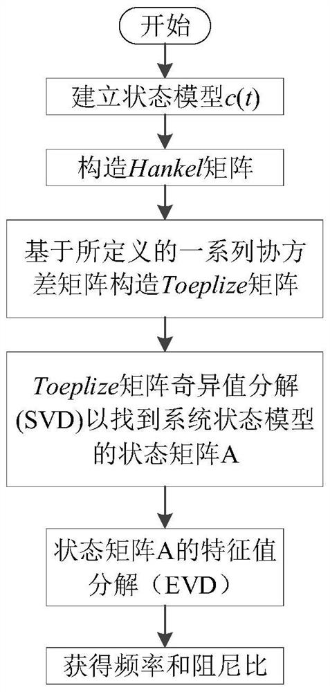
The invention relates to a method for identifying modal parameters of an oscillation signal. The method comprises the following steps: acquiring an original signal of a system, processing the original signal through an empirical mode decomposition method, extracting an intrinsic mode component, and constructing a new signal; processing the new signal by using a random subspace identification method to obtain the frequency and damping ratio of the system; processing the new signal by adopting a Prony method to obtain the frequency, the amplitude and the phase angle of the system; and on the basis of the same frequency rule, pairing the modal parameters obtained by the random subspace identification method and the Prony method to obtain complete and accurate modal parameters. Compared with the prior art, the method has the advantages that the oscillation signal is subjected to stabilization processing by using the empirical mode decomposition method, the sensitivity of the Prony algorithm to noise is overcome, the false mode generated by the random subspace algorithm in processing nonlinear and non-stable signals is avoided, the mode identification is performed by fusing the random subspace identification method and the Prony method, and the mode parameter identification precision is improved.

Description

technical field [0001] The invention relates to the field of identification of oscillation mode parameters, in particular to an identification method of oscillation signal mode parameters. Background technique [0002] With the continuous advancement of power technology, the interconnection of large power grids has been gradually realized, coupled with the widespread use of fast and high-magnification excitation devices, the resulting low-frequency oscillation problems occur from time to time. Low-frequency oscillations usually occur on long-distance, heavy-duty transmission lines, or weak tie lines of interconnected systems, and are more likely to occur under the conditions of a fast-response high-amplification excitation system. The time constant of the fast excitation regulator is greatly reduced, which effectively improves the voltage regulation characteristics, but the additional damping generated by it is negative, which offsets the inherent positive damping of the sys...

Claims


Application Information

Patent Timeline
IPC IPC(8): G06K9/00
CPCG06F2218/06G06F2218/10
Inventor 费成巍李桓刘皓天
Owner FUDAN UNIV
Learn More