Line recognition module and preparation method thereof, and display device

A texture and module technology, applied in the field of texture recognition, can solve the problems of inconsistent peeling speed, large deformation of flexible substrates, and difficult alignment, so as to avoid peeling damage, improve peeling yield, and improve the effect of manufacturing yield.

Pending Publication Date: 2021-07-23
BEIJING BOE SENSOR TECH CO LTD +1
View PDF0 Cites 0 Cited by
  • Summary
  • Abstract
  • Description
  • Claims
  • Application Information

AI Technical Summary

Problems solved by technology

There are two ways to peel off the flexible substrate from the carrier glass: 1. First peel off the flexible substrate, and then bond the FPC after attaching the support film. The FPC pins cannot correspond to the electrical connection, which will cause some channels to fail to conduct; it will also lead to a decrease in the flatness of the flexible substrate after peeling off, difficulty in alignment, and poor lamination effect of subsequent lamination of other film layers
2. First bind the FPC and then peel off the flexible substrate. However, after the thermocompression bonding process, the colloidal state between the flexible substrate and the glass changes, the viscosity becomes larger, it is more difficult to peel off, and it will also cause binding areas and non-binding The colloidal adhesion between the flexible substrate and the glass in the area is inconsistent, and the peeling speed will be inconsistent, which is also not conducive to peeling and affects the peeling yield.

Method used


Image

  • Line recognition module and preparation method thereof, and display device
  • Line recognition module and preparation method thereof, and display device
  • Line recognition module and preparation method thereof, and display device

Examples


Embodiment Construction

[0046] In order to make the purpose, technical solutions and advantages of the embodiments of the present application clearer, the technical solutions of the embodiments of the present application will be clearly and completely described below in conjunction with the drawings of the embodiments of the present application. Apparently, the described embodiments are some of the embodiments of the present application, but not all of them. And in the case of no conflict, the embodiments in the present application and the features in the embodiments can be combined with each other. Based on the described embodiments of the present application, all other embodiments obtained by persons of ordinary skill in the art without creative efforts shall fall within the protection scope of the present application.

[0047] Unless otherwise defined, the technical terms or scientific terms used in the application shall have the ordinary meanings understood by those skilled in the art to which th...


PUM


Abstract

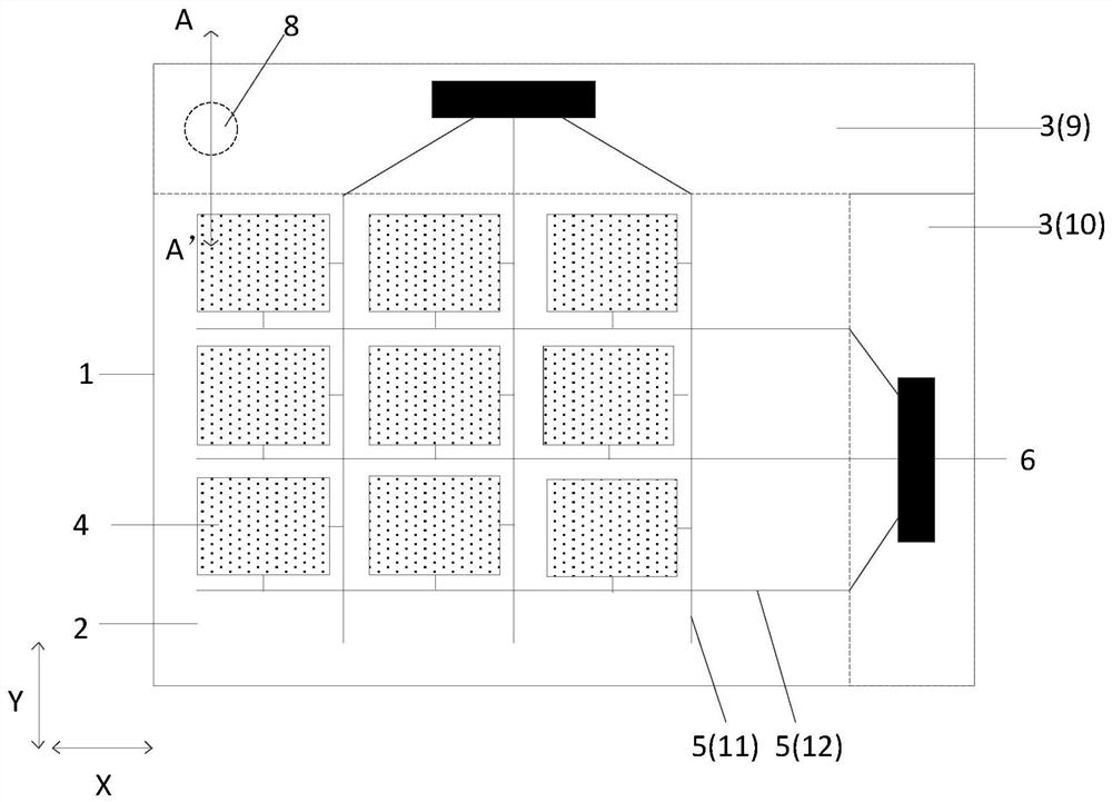
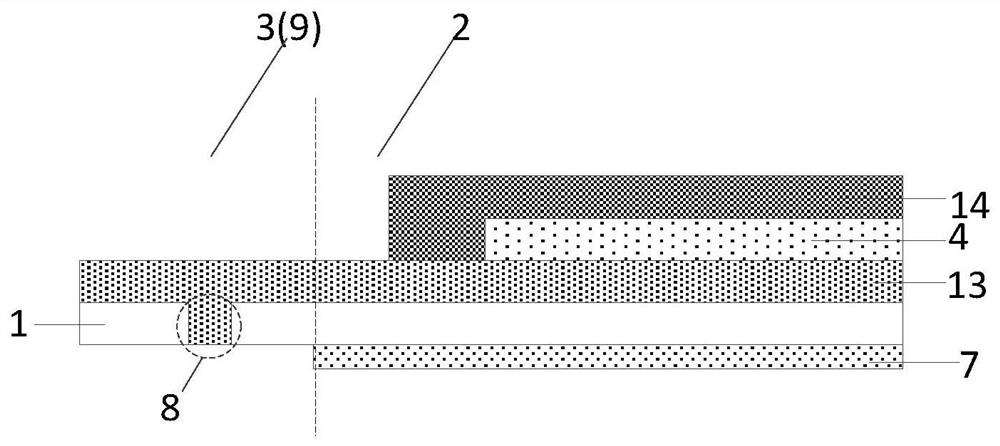
The invention discloses a line recognition module and a preparation method thereof, and a display device, and aims to improve the stripping yield. The embodiment of the invention provides a line recognition module. The line recognition module comprises a flexible substrate which comprises a line recognition area and a binding area located outside the line recognition area; a plurality of line recognition units which are located on one side of the flexible substrate in the line recognition area; a plurality of signal lines which are located on the same side of the flexible substrate as the pattern recognition units and electrically connected with the pattern recognition units, each signal line extending to the binding area from the pattern recognition area; a driving chip which is bound with the signal line in the binding area; and an adhesive layer which is located on the side, away from the line recognition units, of the flexible substrate, the orthographic projection of the adhesive layer on the flexible substrate being not overlapped with the binding area.

Description

technical field [0001] The present application relates to the technical field of texture recognition, in particular to a texture recognition module, a preparation method thereof, and a display device. Background technique [0002] Optical fingerprint under the screen is currently the mainstream solution for mobile phone fingerprint recognition. In order to cope with the narrow space inside the mobile phone and use it in curved screen, folding screen, and scroll screen mobile phones, fingerprint recognition devices with flexible substrates are bound to be adopted. To make a fingerprint identification device with a flexible substrate, the flexible substrate needs to be attached to a glass carrier. After depositing each functional film layer of the fingerprint identification device, it needs to be electrically connected to the flexible circuit board (FPC) through a thermocompression bonding process. The flexible substrate is peeled from the carrier glass. There are two ways to...

Claims


Application Information

Patent Timeline
Patent Type & Authority Applications(China)
IPC IPC(8): H01L25/16H01L21/683H01L21/50G06K9/00
CPCH01L25/16H01L25/167H01L21/6835H01L21/50H01L2221/68386H01L2221/68318G06V40/13
Inventor 范路遥徐帅赵斌赵镇乾代翼
Owner BEIJING BOE SENSOR TECH CO LTD
Why Eureka
Try Eureka