Charge-discharge control method for large-scale energy storage system

A charge and discharge control and energy storage system technology, applied in the direction of circuit devices, AC network circuits, AC network load balancing, etc., can solve the problem that the system stability is greatly affected, the state of charge of the energy storage unit is out of bounds, and the fault cannot be controlled again. problems, to avoid system instability, prolong service life and reliability, and achieve the effect of state-of-charge recovery capability

Inactive Publication Date: 2021-07-23
CHANGSHA UNIVERSITY OF SCIENCE AND TECHNOLOGY
View PDF0 Cites 0 Cited by
  • Summary
  • Abstract
  • Description
  • Claims
  • Application Information

AI Technical Summary

Problems solved by technology

[0006] In order to overcome the shortcomings of the above-mentioned prior art, the present invention provides a large-scale energy storage system charging and discharging control method to solve some defects of the existing energy storage unit control method, such as a great impact on the system stability, failure to fail Control again, there is no reasonable solution after the state of charge of the energy storage unit exceeds the limit

Method used


Image

  • Charge-discharge control method for large-scale energy storage system
  • Charge-discharge control method for large-scale energy storage system
  • Charge-discharge control method for large-scale energy storage system

Examples


Embodiment Construction

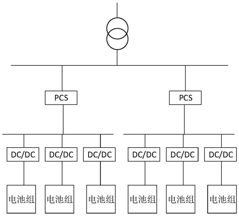
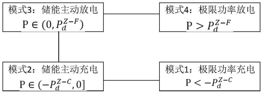
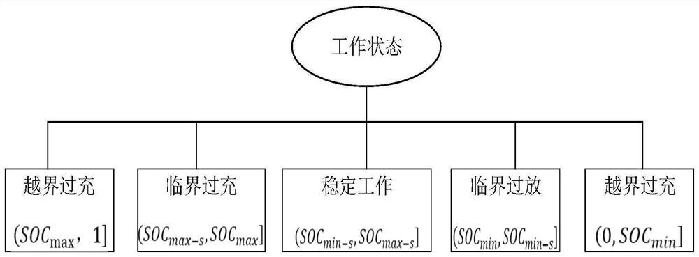
[0014] Depend on figure 2 It can be seen that according to the energy storage system power required for dispatching, the operating state of the energy storage system can be divided into four working modes: limit power charging, energy storage active charging, energy storage active discharge and limit power discharge. Mode 1 and Mode 4, the energy storage system uses the limit charge and discharge power to meet the power required for dispatching. In Modes 2 and 3, the power required for dispatch is within the limit charge and discharge power range of the energy storage system. Active charging and discharging. Generally, in order to ensure the effective and stable operation of the energy storage unit group and prolong its service life, it is necessary to make the energy storage unit operate in the normal working area. In order to prevent the state of charge of the energy storage unit group from exceeding the limit of normal operation, this The invention proposes power flow con...


PUM


Abstract

The invention relates to a charge-discharge control and power distribution method for an energy storage unit group in a large-scale energy storage system, which comprises the following steps of receiving the total power demand of an energy storage power station according to superior scheduling, dividing the energy storage power station into four working modes, and further subdividing the working modes according to the charge state of the energy storage unit group. On the basis, power flow control among the energy storage unit groups is provided, and under the condition that normal power balance of the system is not affected, the critical unit group is controlled to perform reverse power flow, so that the charge state of the critical unit group approaches a stable operation interval, overcharge and overdischarge are avoided, and the service life of a battery is prolonged. And then, for the distribution problem of reverse flow power and total demand power, a power distribution strategy based on chargeable and dischargeable electric quantities and limit power is put forward, firstly, power distribution is conducted according to the proportion of the chargeable and dischargeable electric quantities of each unit group, and if the limit power of the unit group is exceeded at the moment, power distribution is conducted according to the proportion of the limit power of each unit group, and the condition of power over-limit is avoided.

Description

technical field [0001] The invention relates to the technical field of large-scale energy storage control, in particular to a large-scale energy storage system charge and discharge control and power distribution. Background technique [0002] As solar energy, wind energy and other new energy power generation accounts for an increasing proportion in the power grid, and these new energy power generation is volatile, random and intermittent, so in order to improve the power quality, improve the utilization rate of new energy power generation and For power supply reliability, large-scale energy storage power stations are usually established to maintain the power dynamic balance of the grid. [0003] Due to the different charging and discharging conditions of each energy storage unit group in a large-scale energy storage power station, the aging degree of the battery is different, resulting in the different state of charge (SOC) of each energy storage unit group, which is prone t...

Claims


Application Information

Patent Timeline
Patent Type & Authority Applications(China)
IPC IPC(8): H02J3/32H02J3/38
CPCH02J3/32H02J3/38H02J2203/20
Inventor 张嘉诚邓子豪张育粱
Owner CHANGSHA UNIVERSITY OF SCIENCE AND TECHNOLOGY
Why Eureka
Try Eureka