
Novel permanent magnet synchronous motor rotor structure

A permanent magnet synchronous motor and rotor structure technology, which is applied to synchronous machines, magnetic circuit shape/style/structure, control generators, etc., can solve the problems of difficult adjustment of the permanent magnet magnetic field, wide range of motor speed regulation, etc. The effect of large direct axis armature reaction, enhanced structural strength, and expanded speed regulation range

Pending Publication Date: 2021-07-23
HARBIN UNIV OF SCI & TECH
View PDF0 Cites 0 Cited by
  • Summary
  • Abstract
  • Description
  • Claims
  • Application Information

AI Technical Summary

Problems solved by technology

[0003] However, due to the difficulty in adjusting the magnetic field of permanent magnets, many occasions require a wide range of motor speed regulation, which limits the further application of permanent magnet synchronous motors to occasions with high speed regulation range requirements such as CNC machine tool spindle systems and electric vehicle drive systems.

Method used


Image

  • Novel permanent magnet synchronous motor rotor structure

Examples


Embodiment Construction

[0012] The present invention will be further described in detail below with reference to the accompanying drawings and specific embodiments.

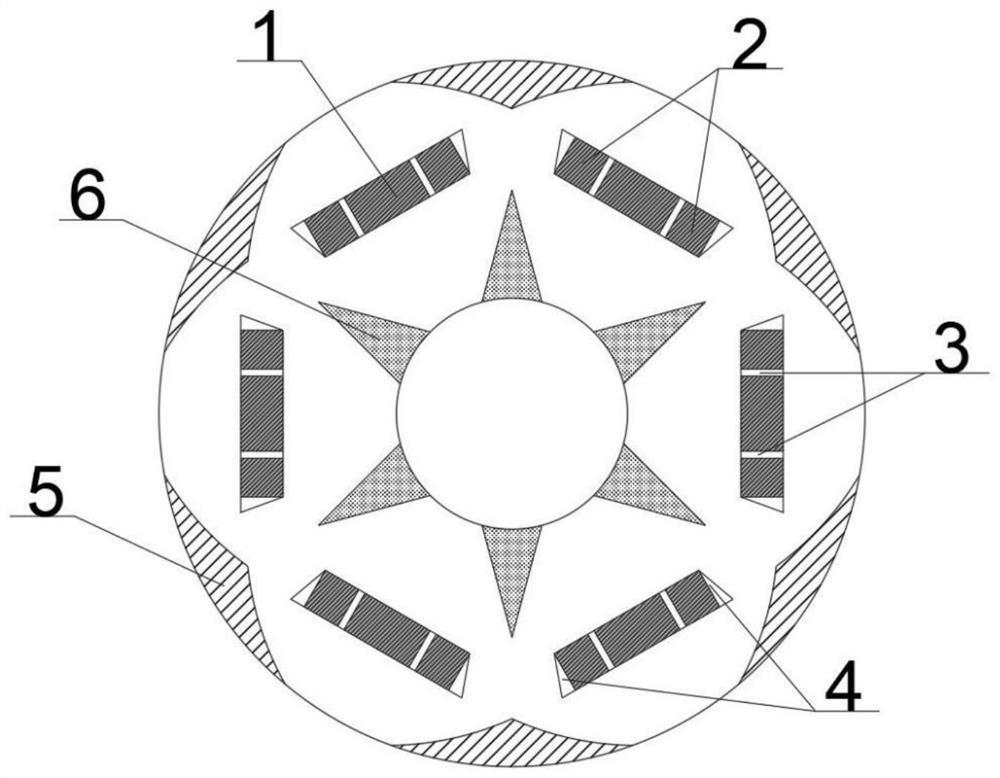
[0013] refer to figure 1 As shown in the figure, a new type of permanent magnet synchronous motor rotor structure adopts the technical scheme as follows: the motor rotor has a 6-pole structure, the 6-pole magnetic circuit is completely symmetrical, and the permanent magnet of each pole is a segmented structure, which is composed of three permanent magnets. There are main permanent magnets and auxiliary permanent magnets, each pole permanent magnet is embedded with a soft iron and a magnetic isolation baffle, a magnetic barrier is embedded on the outside of the rotor, and a non-magnetic conductive material is embedded on the inside of the rotor.

[0014] refer to figure 1 As shown, the ratio of the length of the main permanent magnet to the auxiliary permanent magnet of the motor is 2:1, the main permanent magnet is located in the middl...


PUM


Abstract

The invention relates to the technical field of motors, and provides a novel permanent magnet synchronous motor rotor structure. The structure is high in motor rotor structural strength and wide in flux-weakening speed regulation range. The motor rotor is of a six-pole structure, six-pole magnetic circuits are completely symmetrical, each pole of permanent magnet is of a sectional structure and is composed of three permanent magnets including a main permanent magnet and an auxiliary permanent magnet, magnetism-assisting soft iron and a magnetism-isolating baffle are embedded in each pole of permanent magnet, a magnetic barrier is embedded in the outer side of the rotor, and a non-magnetic material is embedded in the inner side of the rotor. The permanent magnets are embedded into the magnetism-assisting soft iron in a segmented mode, the structural strength is improved, the motor is more suitable for running at a high speed, the magnetic flux leakage of the motor is reduced through the magnetism-isolating baffles, and the fundamental waveform of an air-gap magnetic field is optimized. The magnetic barrier and the non-magnetic conductive material further enhance the structural strength of the motor rotor, improve the air-gap flux density waveform of the motor, reduce the air-gap magnetic field harmonic wave and torque ripple of the motor, and facilitate the expansion of the speed regulation range of the motor.

Description

technical field [0001] The invention relates to the technical field of motors, in particular to a novel permanent magnet synchronous motor rotor structure. Background technique [0002] With the development of permanent magnet materials, permanent magnet synchronous motors with the advantages of simple structure, reliable operation, small size, light weight, high efficiency and power density are increasingly widely used in equipment manufacturing, rail transit, new energy and other fields. [0003] However, due to the difficulty in adjusting the magnetic field of permanent magnets, many occasions require a wide range of motor speed regulation, which limits the further application of permanent magnet synchronous motors in CNC machine tool spindle systems and electric vehicle drive systems where the speed regulation range is high. It has far-reaching significance to provide a new type of permanent magnet synchronous motor rotor structure with high structural strength and wide ...

Claims


Application Information

Patent Timeline
Patent Type & Authority Applications(China)
IPC IPC(8): H02K1/27H02P21/02
CPCH02K1/27H02K21/028H02K2213/03
Inventor 王天宇朱博房志寒徐维豪
Owner HARBIN UNIV OF SCI & TECH
Learn More