Control circuit, control method and resonant converter

A technology of resonant converter and control circuit, which is applied in the field of control circuit and resonant converter, can solve the problem of capacitor CR voltage resonating to too high voltage, and achieve the effect of avoiding the effect of resonant capacitor voltage overshoot

Pending Publication Date: 2021-07-23
SILERGY SEMICON TECH (HANGZHOU) CO LTD
View PDF8 Cites 0 Cited by
  • Summary
  • Abstract
  • Description
  • Claims
  • Application Information

AI Technical Summary

Problems solved by technology

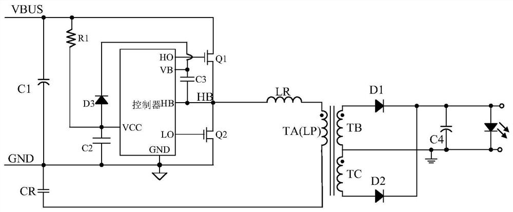
However, in this way, when the lower transistor Q2 is turned on, the resonant network composed of the inductor LR and the capacitor CR will have a large resonance energy, especially the half-bridge midpoint HB of the half-bridge structure composed of the upper transistor Q1 and the lower transistor Q2. When the initial value of the voltage is close to the input voltage Vbus, the lower tube Q2 is always on, and the voltage of the capacitor CR will resonate to an excessive voltage

Method used


Image

  • Control circuit, control method and resonant converter
  • Control circuit, control method and resonant converter
  • Control circuit, control method and resonant converter

Examples


Embodiment Construction

[0037] The present invention is described below based on examples, but the present invention is not limited to these examples. In the following detailed description of the invention, some specific details are set forth in detail. The present invention can be fully understood by those skilled in the art without the description of these detailed parts. In order not to obscure the essence of the present invention, well-known methods, procedures, procedures, components and circuits have not been described in detail.

[0038] Additionally, those of ordinary skill in the art will appreciate that the drawings provided herein are for illustrative purposes and are not necessarily drawn to scale.

[0039]Meanwhile, it should be understood that in the following description, "circuit" refers to a conductive loop formed by at least one element or sub-circuit through electrical connection or electromagnetic connection. When an element or circuit is said to be "connected to" another elemen...


PUM


Abstract

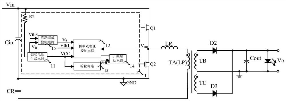
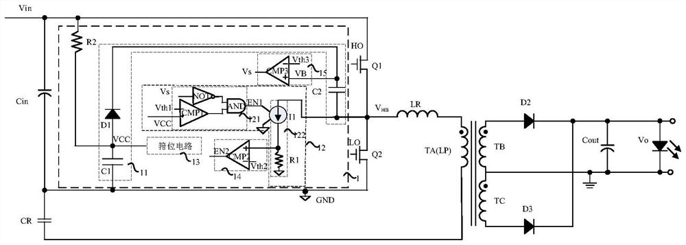
The invention discloses a control circuit, a control method and a resonant converter. The resonant converter comprises a first power switch and a second power switch, wherein the first power switch and the second power switch are sequentially connected in series and coupled between the high potential end of the input end of the resonant converter and a ground potential. The control circuit comprises a bridge midpoint voltage control circuit. In the starting process of the resonant converter, bridge midpoint voltage is controlled to prevent the voltage of a resonant capacitor from being too high during the conduction period of the second power switch, and the bridge midpoint voltage is configured to be the voltage of the common end of the first power switch and the second power switch.

Description

technical field [0001] The present invention relates to the technical field of power electronics, and more specifically, relates to a control circuit, a control method and a resonant converter. Background technique [0002] figure 1 It is a schematic circuit diagram of an LLC resonant converter in the prior art. exist figure 1 In the control scheme of the resonant converter shown, after the system is powered on, the capacitor C2 is charged; after the voltage VCC at the common terminal of the capacitor C2 and the diode D3 reaches the first voltage threshold, the lower transistor Q2 is turned on, and the capacitors C2 and C3 are charged ; When the voltage VB at the common terminal of the capacitor C3 and the diode D3 is charged to the second threshold voltage, the resonant converter starts to work normally. However, in this way, when the lower transistor Q2 is turned on, the resonant network composed of the inductor LR and the capacitor CR will have a large resonance energy...

Claims


Application Information

Patent Timeline
Patent Type & Authority Applications(China)
IPC IPC(8): H02M3/335H02M7/48H02M7/5375H02M7/5387H02M1/088H02M1/36
CPCH02M3/33569H02M7/48H02M7/5375H02M7/5387H02M1/088H02M1/36Y02B70/10H02M3/01H02M7/4815H02M1/0006H02M1/32H02M1/08H02M1/0058
Inventor 王龙奇王翰祥
Owner SILERGY SEMICON TECH (HANGZHOU) CO LTD
Why Eureka
Try Eureka