Camera device and assembling method thereof

A camera and camera component technology, applied in the field of cameras, can solve the problems of difficult to improve the efficiency of camera assembly, difficult to meet the cost of use by consumers, and poor user experience, so as to solve the problem of high prices, saving material costs, and structural design. Reasonable and clever effect

Pending Publication Date: 2021-07-23
东莞市里鹏模具开发有限公司
View PDF5 Cites 0 Cited by
  • Summary
  • Abstract
  • Description
  • Claims
  • Application Information

AI Technical Summary

Problems solved by technology

[0005] Due to the extremely high usage rate of screws and threads in traditional camera equipment with the function of changing the shooting angle, on the one hand, it is difficult to improve the assembly efficiency of the camera; Interference, which in turn brings the problems of high material cost and cumbersome assembly steps;
[0006] In addition, the traditional camera equipment has weak fill light, and in some usage scenarios, artificial fill light is required, which is inconvenient to use and brings a poor user experience to users;
[0007] At present, the industry has basically stopped innovating on the structure of this type of camera, and the production cost and assembly process have been basically finalized, which makes the price of this type of camera equipment with the function of changing the shooting angle remain high, the profit of the manufacturer is not high, and the cost of use of consumers is low. It is also difficult to meet psychological expectations

Method used


Image

  • Camera device and assembling method thereof
  • Camera device and assembling method thereof
  • Camera device and assembling method thereof

Examples


Embodiment Construction

[0057] In order to make the above objects, features and advantages of the present invention more comprehensible, specific implementations of the present invention will be described in detail below in conjunction with the accompanying drawings. In the following description, numerous specific details are set forth in order to provide a thorough understanding of the present invention. However, the present invention can be implemented in many other ways different from those described here, and those skilled in the art can make similar improvements without departing from the connotation of the present invention, so the present invention is not limited by the specific embodiments disclosed below.

[0058] In describing the present invention, it is to be understood that the terms "upper", "lower", "front", "rear", "left", "right", "vertical", "horizontal", "top", The orientation or positional relationship indicated by "bottom", "inner", "outer", etc. is based on the orientation or po...


PUM


Abstract

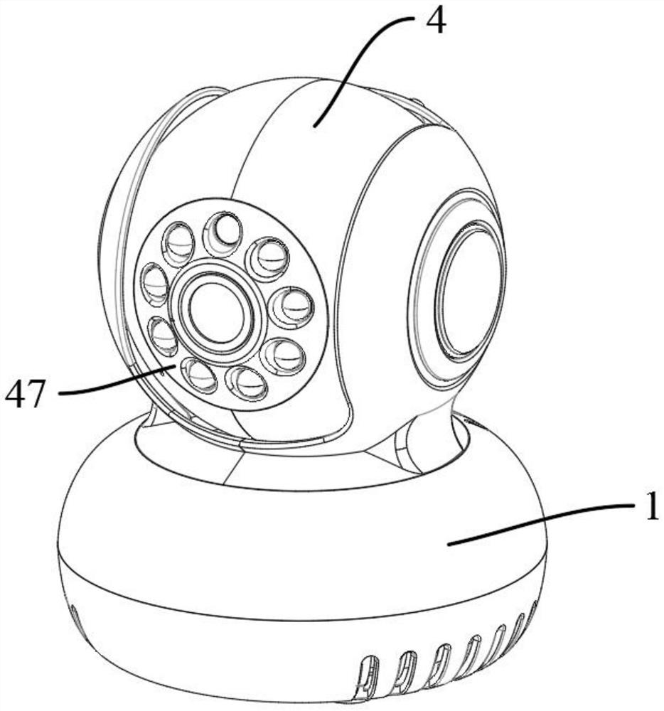
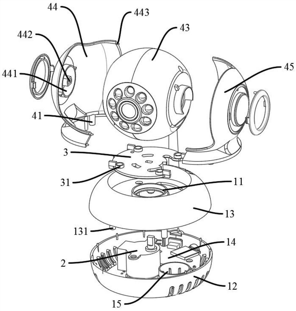
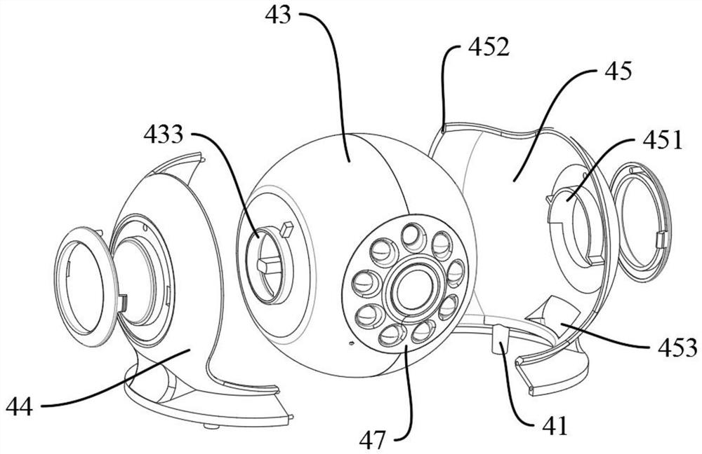
The invention discloses a camera device and an assembling method thereof, and the camera device comprises a mounting base; a first rotating motor clamped in the mounting base; a rotating disc which is connected with a rotating shaft of the first rotating motor and is provided with a plurality of first clamping sleeves; and a camera component, wherein the lower end of the camera component extends to form a first clamping column so as to be inserted and fixed in the first clamping sleeve, a rotary positioning ring is arranged on the mounting base, the lower end of the rotary table is bent downwards to form a plurality of elastic barbs, and the elastic barbs penetrate through the inner side of the rotary positioning ring and are arranged on the lower end face of the rotary positioning ring in a sliding mode. The camera device is reasonable and ingenious in structural design, rapid assembly of the camera device is achieved, the assembly steps are simplified on the premise that the rotating disc is reserved, a large amount of material cost is saved on the premise that the rotating stability is guaranteed, the assembly steps are simplified, dependence on screws and nuts is avoided, and the problem that a camera device with a shooting view angle changing function is high in price is effectively solved.

Description

technical field [0001] The invention relates to the field of camera technology, in particular to a camera device and an assembly method thereof. Background technique [0002] With the development of communication technology, people use computers, remote monitoring and other electronic equipment more and more widely in their daily life. [0003] The camera is the main electronic component that realizes the shooting function of the electronic device, and is also one of the indispensable electronic components. At present, most of the cameras on the market are connected by wires. The use of the camera requires long-term power supply, which involves a lot of wires and layout problems; it brings a lot of inconvenience to the installation and affects the appearance at the same time, so the wireless camera came into being; [0004] In the process of realizing the technical solution of the invention in the embodiment of the application, the inventor of the application found that the...

Claims


Application Information

Patent Timeline
IPC IPC(8): H04N5/225H04N5/235G03B15/02
CPCG03B15/02H04N23/50H04N23/56H04N23/51H04N23/74
Inventor 盘海里
Owner 东莞市里鹏模具开发有限公司
Why Eureka
Try Eureka