Supercharge Your Innovation With Domain-Expert AI Agents!

Bearing assembly for cone crusher

A technology of cone crusher, bearing assembly, applied in the direction of bearings, bearings, shafts and bearings of rotating motion

Active Publication Date: 2021-07-23
山特维克SRP股份有限公司
View PDF4 Cites 2 Cited by
  • Summary
  • Abstract
  • Description
  • Claims
  • Application Information

AI Technical Summary

Problems solved by technology

Therefore, the crusher can only withstand low to moderate forces

Method used


Image

  • Bearing assembly for cone crusher
  • Bearing assembly for cone crusher
  • Bearing assembly for cone crusher

Examples


Embodiment Construction

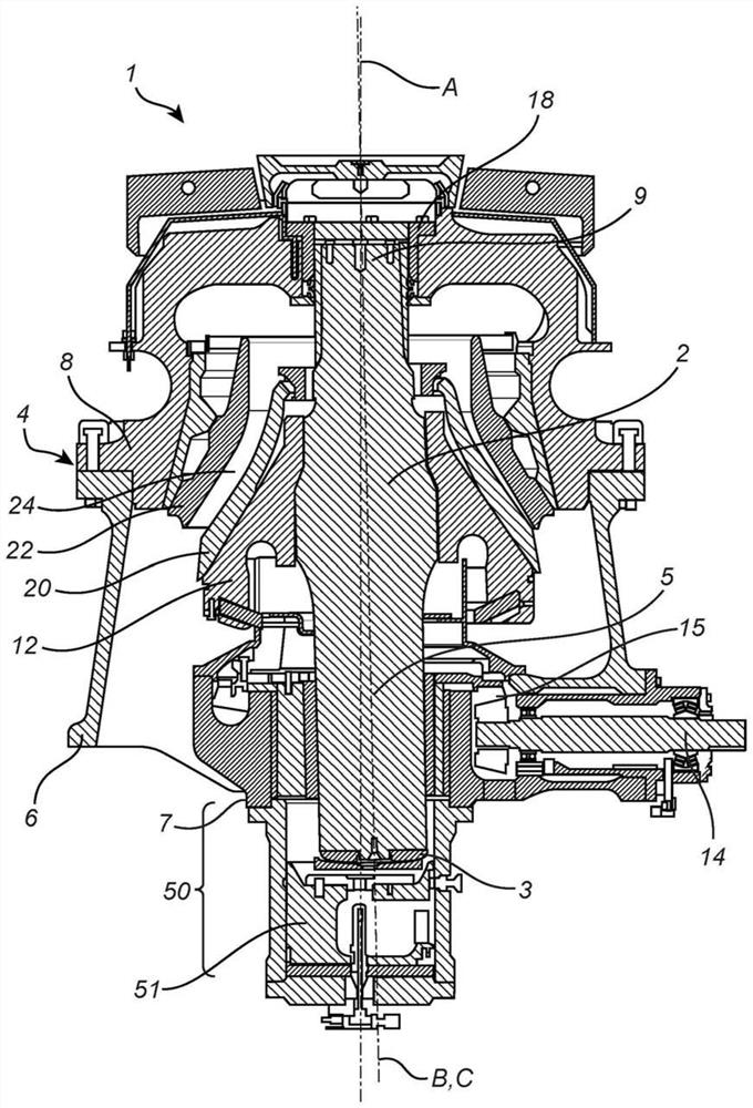
[0028] figure 1 A cone crusher 1 is disclosed having a vertical crushing head shaft 2 and a frame 4 with a bottom 6 and a top 8 . The breaker head shaft 2 has a lowermost end 3 arranged in connection with a hydrodynamic setting assembly 50 and is carried at its uppermost end 9 in a top bearing 18 in the frame top 8 . A crushing head 12 is mounted on the top of the head shaft 2 . The lowermost part 7 of the frame 4 is also arranged in connection with the hydraulic setting assembly 50 .

[0029] An eccentric sleeve 10 is arranged around the lower part 5 of the head shaft 2 . A drive shaft 14 is arranged to rotate the eccentric sleeve 10 via a motor (not shown) and a ring gear 15 mounted on the eccentric sleeve 10 . When the crusher is in operation, the drive shaft 14 rotates the eccentric sleeve 10 so that the crushing head shaft 2 and the crushing head 12 will perform a rotary motion.

[0030] The crushing head shaft 2 is radially supported at its lower part 5 in the eccent...


PUM


Abstract

A bearing assembly for a cone crusher (1) comprises: an inner slide bearing (30), an eccentric sleeve (10) and an outer slide bearing (40) for supporting a lower portion (5) of a crushing head shaft (2), wherein the inner slide bearing (30) has a diameter D1 and an axial height H1 being defined from the inner slide bearing upper end (30a) to the inner slide bearing lower end (30b) and the outer slide bearing (40) has a diameter (D2) and an axial height (H2) being defined from the outer slide bearing upper end (40a) to the outer slide bearing lower end (40b), and wherein the ratio of the inner slide bearing axial height and its diameter H1 / D1 is in the range of (0,95) to (1,20). Further, a cone crusher (1) comprises a bearing assembly.

Description

technical field [0001] The invention relates to a bearing assembly for a cone crusher. Furthermore, the invention relates to a cone crusher. [0002] Cone crushers generally have a pressure relief system that can adjust and control the size of the crushing gap in the vertical direction by means of hydraulic fluid. This is called a hydroset assembly. Background technique [0003] Cone crushers are used to crush ore, mineral and rock materials into smaller sizes. A gyratory crusher is an example of a cone crusher. Typically, the crusher comprises a crushing head mounted on an elongated main shaft. The first crushing shell is mounted on the crushing head, and the second crushing shell is mounted on the frame, so that the first crushing shell and the second crushing shell together define a crushing gap through which the material to be crushed passes. The drive means are arranged to rotate the eccentric assembly around the lower part of the shaft, causing the crushing head t...

Claims


Application Information

Patent Timeline
Patent Type & Authority Applications(China)
IPC IPC(8): B02C2/04
CPCB02C2/04B02C2/047F16C17/12
Inventor 弗雷德里克·埃里克松扬·约翰松索菲耶·尼曼贡纳松
Owner 山特维克SRP股份有限公司
Features
  • R&D
  • Intellectual Property
  • Life Sciences
  • Materials
  • Tech Scout
  • Unparalleled Data Quality
  • Higher Quality Content
  • 60% Fewer Hallucinations
Learn More