Radial artery hemostasis compression belt assembly with pressure indication function
A radial artery, indicating technology, applied to tourniquets and other directions, can solve the problems of inconvenient adjustment and fixation, poor hemostasis effect, insufficient safety, etc., and achieve the effects of good hemostasis effect, high success rate and convenient operation.
- Summary
- Abstract
- Description
- Claims
- Application Information
AI Technical Summary
Problems solved by technology
Method used
Image
Examples
Embodiment 1
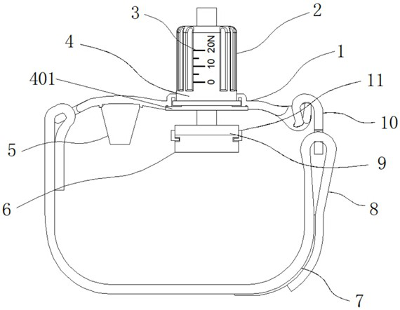
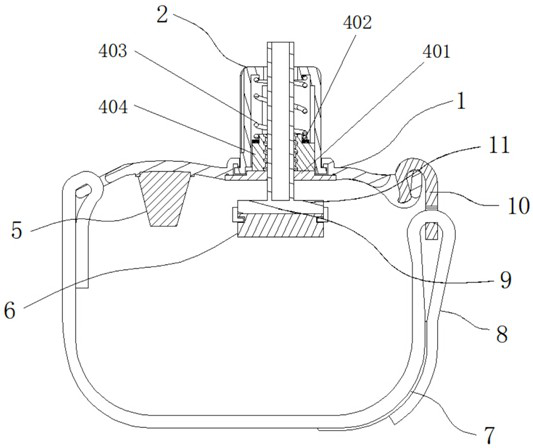
[0028] Example 1: See Figure 1-4 , a radial artery hemostatic compression belt assembly with pressure indication, including a fixed plate 1 and a rotating cap 2, the top of the fixed plate 1 is movably connected with a rotating cap 2, the two ends of the rotating cap 2 are provided with a pressure scale 3, and the rotating cap 2 The inside of the rotating cap 2 is provided with a spinning structure 4, the inside of the rotating cap 2 is vertically provided with a screw rod 9, the bottom end of the screw rod 9 is fixedly connected with an elastic body 6, and the bottom end of the fixed plate 1 is provided with a fixed structure;
[0029] see Figure 1-4 A radial artery hemostatic compression belt assembly with pressure indication also includes a fixing structure, the fixing structure includes a support pad 5, the support pad 5 is fixedly connected to the bottom end of one side of the fixing plate 1, and one side of the fixing plate 1 is fixedly connected to a fixed With 8, th...
Embodiment 2
[0033] Embodiment 2: The bottom end of the screw rod 9 is a cuboid, and the bottom ends of the elastic body 6 and the screw rod 9 are equal in length and width;
[0034] The top of the fixed plate 1 is provided with a movable groove, and the bottom end of the rotating cap 2 is embedded in the movable groove and is movably connected with the fixed plate 1 through the movable groove;
[0035] Both sides of the exterior of the rotating cap 2 are provided with non-slip threads, and the support pad 5 and the elastic body 6 are made of silica gel;
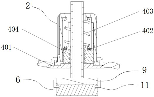
[0036] Specifically, such as figure 1 , figure 2 , image 3 and Figure 4 As shown, the medical personnel twist the rotating cap 2 to drive the screw rod 9 to move up and down. During the operation, it rotates clockwise, the screw rod 9 is pressed down, and the screw rod 9 is turned counterclockwise to rise, and the internal pressure of the rotating cap 2 drives the indicator ring 402 to move to indicate the pressure. Scale 3, so th...
Embodiment 3
[0037] Embodiment 3: The spinning structure 4 is composed of a gland 401, an indicator ring 402, a spring 403 and a nut 404. The gland 401 is fixedly connected to the bottom end of the fixed plate 1, and the nut 404 is fixedly connected to the bottom end of the rotating cap 2. An indicator ring 402 is sleeved on the top of the nut 404, and a spring 403 is fixedly connected to the top of the indicator ring 402;
[0038] The middle section of the screw rod 9 is provided with an external thread, and the inside of the nut 404 is provided with an internal thread, and the screw rod 9 vertically penetrates the inside of the rotating cap 2 and is threadedly connected with the nut 404;
[0039] The size of the gland 401 is larger than the bottom end of the rotary cap 2, and the gland 401 is embedded in the movable groove of the fixed plate 1 and fixedly connected with the fixed plate 1;
[0040] Specifically, such as figure 1 , figure 2 , image 3 and Figure 4 As shown, when the me...
PUM
 Abstract
Description
Claims
Application Information
 - R&D
- Intellectual Property
- Life Sciences
- Materials
- Tech Scout
- Unparalleled Data Quality
- Higher Quality Content
- 60% Fewer Hallucinations
Browse by: Latest US Patents, China's latest patents, Technical Efficacy Thesaurus, Application Domain, Technology Topic, Popular Technical Reports.
© 2025 PatSnap. All rights reserved.Legal|Privacy policy|Modern Slavery Act Transparency Statement|Sitemap|About US| Contact US: help@patsnap.com


