Rapid drying device for automobile part paint spraying

A technology for fast drying and auto parts. It is used in devices for coating liquids on surfaces, pretreatment surfaces, coatings, etc. It can solve problems such as shortened paint life, paint wrinkles, paint damage, etc., to reduce mobile operation panels. time, prolong service life and improve work efficiency

Active Publication Date: 2021-07-27
常州市迪福隆光电科技有限公司
3 Cites 0 Cited by

AI-Extracted Technical Summary

Problems solved by technology

[0003] Existing fast dryers use high-temperature heating. Although they can dry quickly, the spray paint will be greatly damaged, which will greatly shorten the life of the spray paint and cause the spray paint to lose its original color. ; The air outlet of the single u...

Method used

1, operating panel 2-1 is close to drying box 3-1, can dry immediately after finishing painting, without additional transfer, avoids destroying painting in the transfer, improves the sp...

Abstract

The invention relates to the technical field of automobile part machining, in particular to a rapid drying device for automobile part paint spraying. A first sliding groove is formed in the rear side of the upper surface of a bottom box, the left end of a lead screw is rotationally connected with the left side wall of the first sliding groove through a bearing, and the right end of the lead screw is rotationally connected through a bearing to penetrate through the right side wall of the first sliding groove and then is fixed to an output shaft of a motor; and the lead screw is sleeved with two nuts in a screwed mode. The motor is connected with an external power supply and is fixed on the right side wall of the bottom box. A second sliding groove is formed in the front side of the upper surface of the bottom box. Drying can be carried out immediately after paint spraying is completed, additional transferring is not needed, paint spraying is prevented from being damaged in the transferring process, and the drying speed is increased; the spray paint is firstly blow-dried and then is heated and dried, great damage caused by heating of the spray paint is avoided, the service life of the spray paint is prolonged, and the practicability is improved; and the extra moving time is shortened, and the working efficiency is improved.

Application Domain

Pretreated surfacesCoatings

Technology Topic

Left lateral wallEngineering +4

Image

  • Rapid drying device for automobile part paint spraying
  • Rapid drying device for automobile part paint spraying
  • Rapid drying device for automobile part paint spraying

Examples

  • Experimental program(1)

Example Embodiment

[0031] The present invention will be further described below in conjunction with the accompanying drawings.
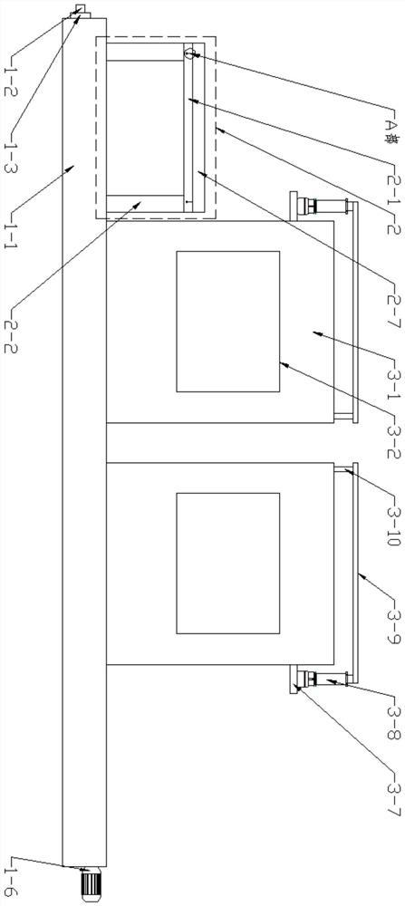
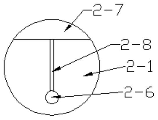
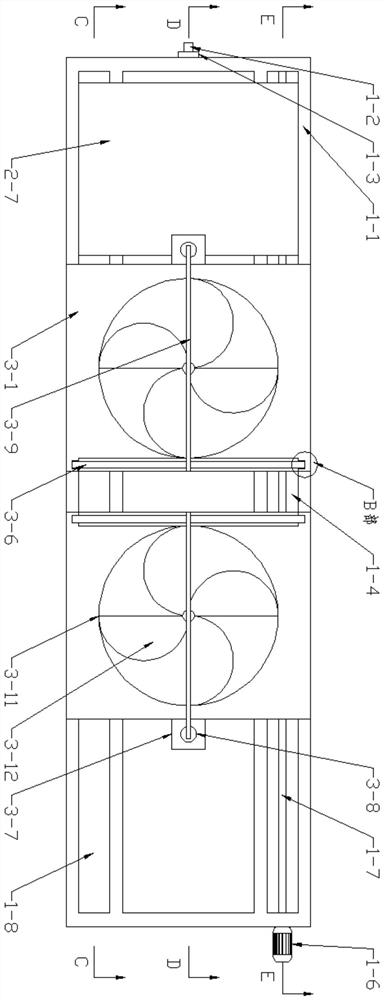
[0032] see as Figure 1 to Figure 10As shown, the technical solution adopted in this specific embodiment is: it includes a support mechanism 1, an operating mechanism 2 and a drying mechanism 3; the support mechanism 1 includes a bottom box 1-1, a drain pipe 1-2, a valve 1- 3. Screw rod 1-5, motor 1-6 and screw nut 1-7; the left side wall of the bottom box 1-1 is connected with a drain pipe 1-2, and the drain pipe 1-2 is provided with a valve 1-3 , regularly open the valve 1-3 to facilitate the cleaning of the bottom box 1-1; the rear side of the upper surface of the bottom box 1-1 is provided with a No. 1 chute 1-4, and the left end of the screw rod 1-5 passes through the bearing and the No. 1 chute The left side wall of 1-4 is screwed, and the right end of screw rod 1-5 is screwed through the bearing to pass through the right side wall of No. 1 chute 1-4, and is welded and fixed with the output shaft of motor 1-6; screw rod 1 -5 There are two screw nuts 1-7 on the upper screw sleeve; the model of the motor 1-6 is ZDY208D, the motor 1-6 is connected to the external power supply, and the motor 1-6 is fixed on the right side of the bottom box 1-1 by bolts On the wall; the front side of the upper surface of the bottom box 1-1 is provided with No. 2 chute 1-8; the upper left end of the bottom box 1-1 is provided with an operating mechanism 2; the operating mechanism 2 includes an operating panel 2-1, a No. support rod 2-2, No. 2 support rod 2-3, walking wheel 2-4, fixed rod 2-5, limit plate 2-6, backing paper 2-7, lanyard 2-8 and elastic ring 2- 9. The rear side of the bottom of the operation panel 2-1 is fixed with two left and right No. 1 support rods 2-2 by bolts. Fixed; the front side of the bottom of the operation panel 2-1 is fixed with two left and right No. 2 support rods 2-3 by bolts, and the No. 2 support rod 2-3 slides and is located in the No. 2 chute 1-8; No. 2 support rod 2 The bottom of -3 is screwed with road wheel 2-4 by axle and bearing, and road wheel 2-4 rolls and is located in the No. two chute 1-8, and road wheel 2-4 helps No. two support bar 2-3 in Move in No. 2 chute 1-8; On the front and rear side walls of the operation panel 2-1, there are two left and right fixed rods 2-5 welded and fixed, and the outer end of the fixed rod 2-5 is welded and fixed to limit the plate 2-6 The operation board 2-1 is laid with pad paper 2-7; the front and rear sides of the pad paper 2-7 are fixed with a lanyard 2-8 by glue, and the other end of the lanyard 2-8 is fixed with an elastic ring by glue 2-9, after the elastic ring 2-9 passes through the limit plate 2-6, it is hung on the fixed rod 2-5; the pad paper 2-7 helps to prevent the spray paint from accumulating on the operation panel 2-1;
[0033] The bottom box 1-1 is provided with a drying mechanism 3; the drying mechanism 3 includes a drying box 3-1, an observation window 3-2, a door body 3-6, a mounting plate 3-7, and an electric telescopic rod 3 -8, No. 1 connecting rod 3-9, No. 2 connecting rod 3-10, fan 3-12 and heating rod 3-13; bottom box 1-1 is provided with left and right two drying boxes 3-1; drying The rear side wall of the box 3-1 is fixed on the rear side wall of the No. 1 chute 1-4 by bolts, and the front side wall of the drying box 3-1 is fixed on the front side wall of the No. 2 chute 1-8 by bolts On the opening of the front and rear side walls of the drying box 3-1, an observation window 3-2 is embedded, and the observation window 3-2 helps to observe the situation in the drying box 3-1; the left and right two drying boxes There is a No. 1 door opening 3-3 on the relative outer wall of the 3-1, and a No. 2 door opening 3-4 is provided on the relative inner walls of the left and right drying boxes 3-1, and the No. 2 door opening 3-4 is set up and down; No. 3 chute 3-5 is provided on the front and rear side walls of No. 2 door opening 3-4, and the front and rear side walls of door body 3-6 are slidably inserted in the front and rear two No. 3 chute 3-5 respectively. 3-5 helps the door body 3-6 to move up and down smoothly; the upper ends of the outer walls of the left and right two drying boxes 3-1 are fixed with mounting plates 3-7 by bolts, and the upper ends of the mounting plates 3-7 are fixed with electric motors by bolts. Telescopic rod 3-8, the model of electric telescopic rod 3-8 is TGA, and electric telescopic rod 3-8 is connected with external power supply; The other end bottom of connecting rod 3-9 is fixed with No. 2 connecting rod 3-10 by bolt, and the bottom of No. 2 connecting rod 3-10 is fixed with door body 3-6 by bolt; There is an installation hole 3-11, and a fan 3-12 is fixed by bolts in the installation hole 3-11, and the fan 3-12 is connected to an external power supply; several heating rods 3-13 are arranged on the front and rear side walls of the drying box 3-1 , the heating rod 3-13 is connected with an external power supply.
[0034] The working principle of this specific embodiment: before spraying the paint, the pad paper 2-7 is laid on the operation panel 2-1, and the elastic ring 2-9 on the lanyard 2-8 on the front and rear sides of the pad paper 2-7 is After passing through the limit plate 2-6, it is hung on the fixed rod 2-5, so that the backing paper 2-7 is fixed on the operation panel 2-1, so as to prevent spray paint from accumulating on the operation panel 2-1; Water is injected into the bottom box 1-1, and the paint dripped from spray paint falls into the water of the bottom box 1-1, and the painting operation is carried out on the operation panel 2-1 first; after the painting is completed, start the fans 3 in the two drying boxes 3-1 -12 and the heating rod 3-13 in the drying box 3-1 on the right side; start the motor 1-6, and the output shaft of the motor 1-6 rotates, so that the screw rod 1-5 rotates, driving the screw nut 1-7 to move , so that the No. 1 support rod 2-2 drives the accessories on the operation panel 2-1 to move, and the travel wheel 2-4 helps the No. 2 support rod 2-3 to move in the No. 2 chute 1-8, and the operation panel 2-1 After moving to the drying box 3-1 on the left, turn off the motor 1-6; the fan 3-12 in the drying box 3-1 on the left blows the air on the surface of the accessories, and sprays the paint on the surface of the accessories. A preliminary blow-drying operation; start the left and right two electric telescopic rods 3-8 at the same time, and the electric telescopic rods 3-8 stretch out, so that the No. 1 connecting rod 3-9 drives the No. 2 connecting rod 3-10 to rise, so that the door body 3 -6 rises, the third chute 3-5 makes the door body 3-6 move up and down smoothly, starts the motor 1-6, moves the operation panel 2-1 to the drying box 3-1 on the right, and starts the electric telescopic rod 3-8, the electric telescopic rod 3-8 is retracted, so that the door body 3-6 is lowered to avoid excessive heat dissipation in the drying box 3-1 on the right; the drying box 3-1 on the right is a pair of accessories The sprayed paint on the surface is heated and blown to dry, avoiding the sprayed paint from being greatly damaged, and speeding up the drying speed; after the drying is completed, turn off the fan 3-12 and the heating rod 3-13, start the motor 1-6, and make the operation panel 2-1 Move to the right, remove the accessories for spraying and drying, and then perform painting operation on the operation panel 2-1 again, repeat the above steps and change the order of left and right, start the fans 3- in the two drying boxes 3-1 12 and the heating rod 3-13 in the drying box 3-1 on the left; start the motor 1-6, move the nut 1-7 to the left, and move the operation panel 2-1 to the drying box 3-1 on the right Carry out a preliminary blow-drying operation on the spray paint on the surface of the accessories, and carry out heating and blowing drying in the drying box 3-1 on the left; after a long time of use, remove the elastic ring 2-9 from the fixing rod 2-5 Next, replace the backing paper 2-7; open the valve 1-3 regularly to release the water to clean the bottom box 1-1.
[0035] After adopting above-mentioned structure, the beneficial effect of this embodiment is:
[0036] 1. The operation panel 2-1 is close to the drying box 3-1, which can be dried immediately after painting, without additional transfer, avoiding damage to the paint during transfer, and improving the drying speed;
[0037] 2. Blow dry first and then heat and dry to avoid great damage to the spray paint due to heat, prolong the service life of the spray paint and improve the practicability;
[0038] 3. It can be operated back and forth on the bottom box 1-1, which reduces the time for additionally moving the operation panel 2-1 and improves work efficiency;
[0039] 4. A replaceable backing paper 2-7 is provided to prevent spray paint from accumulating on the operation panel 2-1.
[0040] The above is only used to illustrate the technical solution of the present invention and not to limit it. Other modifications or equivalent replacements made by those skilled in the art to the technical solution of the present invention should be considered as long as they do not depart from the spirit and scope of the technical solution of the present invention. fall within the scope of the claims of the present invention.

PUM

no PUM

Description & Claims & Application Information

We can also present the details of the Description, Claims and Application information to help users get a comprehensive understanding of the technical details of the patent, such as background art, summary of invention, brief description of drawings, description of embodiments, and other original content. On the other hand, users can also determine the specific scope of protection of the technology through the list of claims; as well as understand the changes in the life cycle of the technology with the presentation of the patent timeline. Login to view more.

Similar technology patents

Method and device for providing voice service

ActiveCN107833574AaccelerateImprove voice service efficiency
Owner:BAIDU ONLINE NETWORK TECH (BEIJIBG) CO LTD +1

Classification and recommendation of technical efficacy words

  • accelerate
  • Extended service life

Three-dimensional circuit manufacturing process and composite components of laser plastic material and manufacturing method

ActiveCN101859613Aaccelerateaccelerated continuous motion
Owner:深圳市微航磁电技术有限公司

Failure recognition method and system based on neural network self-learning

ActiveCN103914735ASpeed ​​up fault identificationaccelerate
Owner:BEIJING TAILEDE INFORMATION TECH

Distributed file system and data access method thereof

InactiveCN103647797Arelieve pressureaccelerate
Owner:BEIJING UNIV OF POSTS & TELECOMM

Fracturing manifold quick connecting device

Owner:YANTAI JEREH PETROLEUM EQUIP & TECH

Modified asphalt composition with creeping characteristic and preparation method thereof

InactiveCN102020859Aavoid rapid agingExtended service life
Owner:ZHEJIANG WOPUMAN HIGH NEW MATERIALS
Why Eureka
Try Eureka