Printing machine and drying device thereof

A technology for drying devices and printing machines, which is applied to printing machines, printing, general parts of printing machinery, etc., and can solve the problems of high drying efficiency, drying efficiency and drying effect, simple structure, etc.

Inactive Publication Date: 2021-07-27
咸阳文绘印刷有限公司
View PDF1 Cites 0 Cited by
  • Summary
  • Abstract
  • Description
  • Claims
  • Application Information

AI Technical Summary

Problems solved by technology

[0003] The pictures and text after printing cannot be dried immediately, and a corresponding drying device needs to be installed, and the drying device will dry the printed product after the printing is completed; a Chinese utility model patent with the publication number CN203331580U discloses a A drying device for a printing machine, comprising a fan, an oven box and a heating box, the fan is connected to the heating box, a heating device is arranged in the heating box, the heating box is connected to the oven box, and the heating box is connected to the oven There are multiple communication channels evenly distributed between the boxes, the air outlets of the channels are flat, the outer body of the oven box is wrapped with asbestos or foam insulation layer, and the heating box is a telescopic structure, the heating device is electrically connected with the constant temperature protector, By placing the heating device in the heating box and communicating with the oven box through multiple communication channels, the temperature in the oven box is uniform and the drying efficiency is high; but its structure is simple, and it is difficult to clean the printed products during actual use. Stable conveying and effective drying, drying efficiency and drying effect need to be improved

Method used


Image

  • Printing machine and drying device thereof
  • Printing machine and drying device thereof
  • Printing machine and drying device thereof

Examples


Embodiment Construction

[0034] In order to make the object, technical solution and advantages of the present invention clearer, the present invention will be further described in detail below in combination with specific embodiments and with reference to the accompanying drawings. It should be understood that these descriptions are exemplary only, and are not intended to limit the scope of the present invention. Also, in the following description, descriptions of well-known structures and techniques are omitted to avoid unnecessarily obscuring the concept of the present invention.

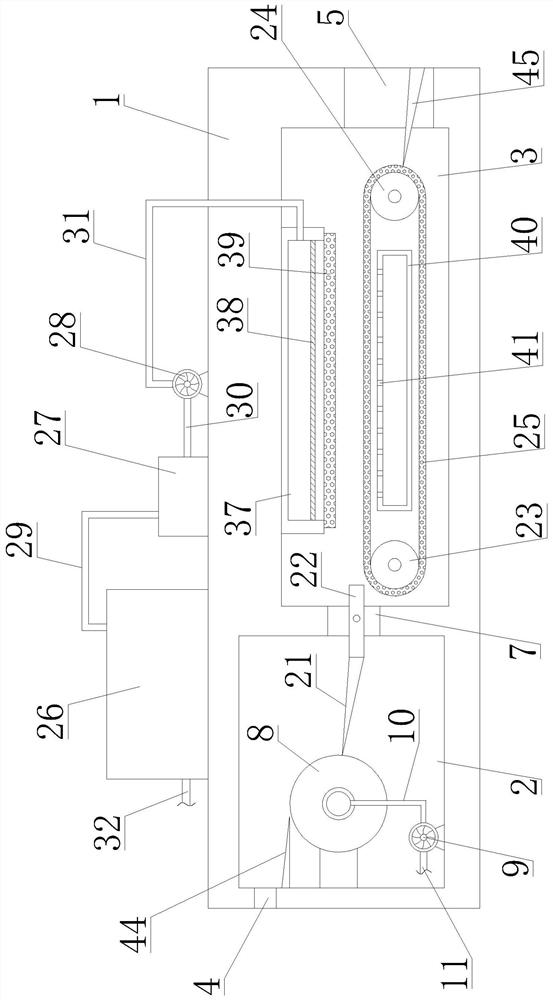
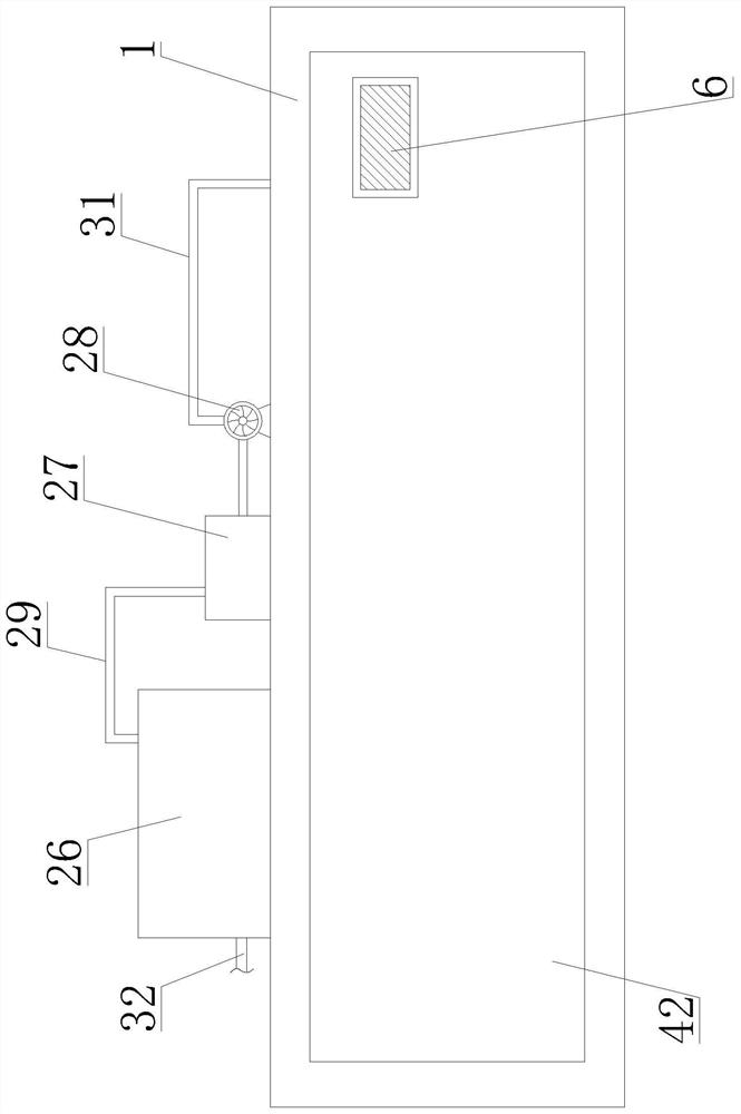
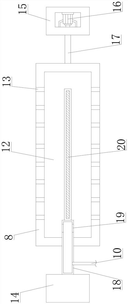
[0035] Such as Figure 1-5 As shown, the present invention proposes a drying device for a printing machine, including a drying box 1, a drying roller 8, a negative pressure pump 9, a first driving device 16, an electric heating tube 20, a material guide plate 22, a conveyor belt 25. Dehumidification box 26, connection box 27, circulation fan 28, first connection pipe 29, circulation pipe 32, first connection box 37, seco...


PUM


Abstract

A drying device of a printing machine comprises a drying box. A first drying chamber and a second drying chamber are arranged in the drying box. A fixed pipe is longitudinally arranged on a first connecting piece, and a rotating shaft is longitudinally arranged on a second connecting piece. A drying roller is arranged on the rotating shaft and rotationally connected with the fixed pipe, a heating cavity is formed in the drying roller, and first air inlet holes are formed in the peripheral surface of the drying roller. An air extraction opening communicates with the heating cavity and the fixed pipe. An air extraction pipe communicates with the fixed pipe. A driving roller and a driven roller are arranged in the second drying chamber. A conveying belt is connected with the driving roller and the driven roller, and through holes are evenly formed in the surface of the conveying belt. An electric heating wire is arranged in a first connecting box, and a gridding air distribution plate is arranged at the bottom of the first connecting box. The invention further provides the printing machine. The printing machine comprises the above drying device of the printing machine. By means of the drying device and the printing machine and the printing machine, printed products can be stably conveyed and can also be effectively dried, the drying efficiency is high, the drying effect is good, hot air can be cyclically utilized, and energy saving and environment protection are achieved.

Description

technical field [0001] The invention relates to the technical field of printing machines, in particular to a printing machine and a drying device thereof. Background technique [0002] A printing machine is a machine for printing text and images. A modern printing machine is generally composed of plate loading, ink application, embossing, paper feeding and other mechanisms. The ink is applied manually or by a printing machine to the place where there are text and images on the printing plate, and then directly or indirectly transferred to paper or other substrates (such as textiles, metal plates, plastics, leather, wood, glass and ceramics) In order to reproduce the same printed matter as the printing plate, the invention and development of the printing press play an important role in the spread of human civilization and culture; [0003] The pictures and text after printing cannot be dried immediately, and a corresponding drying device needs to be installed, and the drying...

Claims


Application Information

Patent Timeline
Patent Type & Authority Applications(China)
IPC IPC(8): B41F23/04
CPCB41F23/0426B41F23/0466
Inventor 赵智曹煜宇金学蔚
Owner 咸阳文绘印刷有限公司
Why Eureka
Try Eureka