
Double-shaft rotational flow energy dissipation spillway tunnel structure

A structural type and technology of flood discharge tunnel, which is applied in the field of double shaft swirl energy dissipation flood discharge tunnel structure type, can solve the problems of poor energy dissipation effect and can not meet flood discharge needs, etc., and achieves the effect of smooth and uniform flow, flexible layout and convenient construction

Active Publication Date: 2021-07-27
POWERCHINA XIBEI ENG
View PDF7 Cites 1 Cited by
  • Summary
  • Abstract
  • Description
  • Claims
  • Application Information

AI Technical Summary

Problems solved by technology

[0004] The purpose of the present invention is to provide a structure type of double-shaft swirling flow energy dissipation flood discharge tunnel to solve the problem that with the increase of water head and flow in the above-mentioned background technology, a single vertical shaft swirl flow discharge tunnel can no longer meet the flood discharge demand and energy dissipation effect poor problem

Method used


Image

  • Double-shaft rotational flow energy dissipation spillway tunnel structure
  • Double-shaft rotational flow energy dissipation spillway tunnel structure
  • Double-shaft rotational flow energy dissipation spillway tunnel structure

Examples


Embodiment Construction

[0023] The following will clearly and completely describe the technical solutions in the embodiments of the present invention with reference to the accompanying drawings in the embodiments of the present invention. Obviously, the described embodiments are only some, not all, embodiments of the present invention. Based on the embodiments of the present invention, all other embodiments obtained by persons of ordinary skill in the art without making creative efforts belong to the protection scope of the present invention.

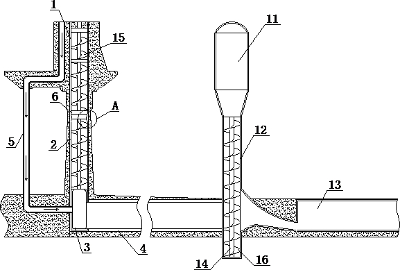
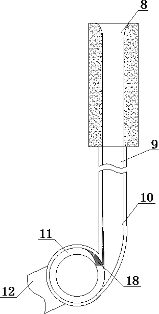
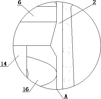
[0024] see Figure 1-4 , the present invention provides a technical solution: a double shaft swirl energy dissipation flood discharge tunnel structure type, including: horizontal swirl water inlet 1, horizontal swirl shaft 2, horizontal swirl swirl chamber 3, horizontal swirl lower flat tunnel 4. Horizontal swirl ventilation shaft 5. Horizontal swirl aeration sill 6. Horizontal swirl baffle sill 7. Vertical swirl inlet sluice section 8. Vertical swirl upper fl...


PUM


Abstract

The invention discloses a double-shaft rotational flow energy dissipation spillway tunnel structure. The double-shaft rotational flow energy dissipation spillway tunnel structure comprises a horizontal rotational flow shaft, wherein the horizontal rotational flow shaft is of an underground reinforced concrete circular section structure, a horizontal rotational flow aerator is fixedly arranged on the inner wall of the horizontal rotational flow shaft, a horizontal rotational flow swirling chamber is fixedly connected to the bottom of the horizontal rotational flow shaft, a horizontal rotational flow lower adit is fixedly installed on the end part of the horizontal rotational flow swirling chamber, and the horizontal rotational flow lower adit is of a reinforced concrete circular section structure which is reconstructed from a diversion tunnel. According to the double-shaft rotational flow energy dissipation spillway tunnel structure, the horizontal rotational flow shaft and a vertical rotational flow shaft are arranged, the flood discharge structure can stably complete rotational flow energy dissipation operation for stable flood discharge even under the condition that water heads and flow are gradually increased, so that the durability and applicability of the device are greatly increased, and a temporary diversion tunnel is rebuilt into a permanent spillway tunnel, so that the spillway tunnel structure has the advantages of flexibility in arrangement, convenience in construction and low manufacturing cost.

Description

technical field [0001] The invention relates to the technical field of water conservancy engineering, in particular to a structural type of a double shaft swirl energy dissipation flood discharge tunnel. Background technique [0002] In the existing water conservancy and hydropower projects, most of the geological conditions are complicated, and the layout of flood discharge and energy dissipation buildings is relatively difficult. Especially for some local material dam hubs, the diversion tunnel engineering volume is relatively large. How to effectively use the diversion tunnel and rebuild it into Spill tunnel is a technical difficulty in engineering design. Although the existing vertical shaft swirl flood discharge tunnel can achieve this effect, with the increase of water head and flow, a single vertical shaft swirl flood discharge tunnel can no longer meet the demand, and the energy dissipation effect of the general swirl energy dissipation flood discharge tunnel structu...

Claims


Application Information

Patent Timeline
Patent Type & Authority Applications(China)
IPC IPC(8): E02B9/04E02B8/06
CPCE02B9/04E02B8/06Y02E10/20
Inventor 周恒陆希狄圣杰黄鹏刘静张莹王卫国尹进步
Owner POWERCHINA XIBEI ENG
Learn More