Flat-pressing and flat-waste-clearing die-cutting machine

A technology for flattening and die-cutting machines, which is applied in metal processing and other directions, and can solve the problem of reducing the scope of application of flattening and flattening die-cutting machines. The flattening and flattening die-cutting machine does not have a fixed adjustment structure and increases the number of users. Operation steps and other issues

Pending Publication Date: 2021-07-30
湖南景呈包装有限公司
View PDF6 Cites 0 Cited by
  • Summary
  • Abstract
  • Description
  • Claims
  • Application Information

AI Technical Summary

Problems solved by technology

[0004] There are certain disadvantages in the existing flat-press flat stripping die-cutting machine during use. The stripping structure of the traditional flat-press flat stripping die-cutting machine adopts a fixed structure design. When the cutting machine performs die-cutting operations of different specifications, the user needs to replace the waste stripping structure of the entire flat-bed flat stripping die-cutting machine in order to complete the die-cutting stripping operations of different specifications, which increases the user's operations At the same time, it reduces the flexibility of the flat-press flat stripping die-cutting machine, making it impossible to perform arbitrary stripping adjustment operations according to the die-cutting structure; secondly, the traditional flat-press flat stripping die-cutting machine does not have a fixed adjustment structure, As a result, it is impossible to make any fixed adjustment structure according to the size of the cardboard, which reduces the scope of application of the flat-bed flat waste stripping die-cutting machine, and brings certain adverse effects to users.

Method used


Image

  • Flat-pressing and flat-waste-clearing die-cutting machine
  • Flat-pressing and flat-waste-clearing die-cutting machine
  • Flat-pressing and flat-waste-clearing die-cutting machine

Examples


Embodiment Construction

[0030]The technical solutions in the embodiments of the present invention will be clearly and completely described below in conjunction with the embodiments of the present invention. Apparently, the described embodiments are only some of the embodiments of the present invention, not all of them. Based on the embodiments of the present invention, all other embodiments obtained by persons of ordinary skill in the art without creative efforts fall within the protection scope of the present invention.

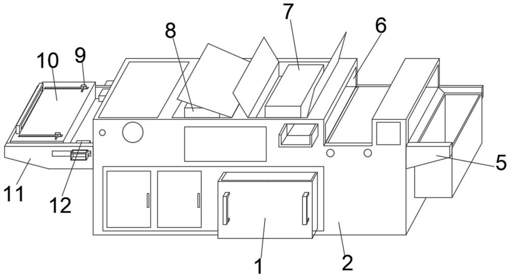
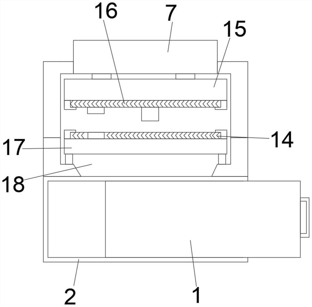
[0031] Such as Figure 1-6 As shown, a flat die-cutting machine for waste stripping includes a box shell 2, a receiving bottom plate 11 and a first hydraulic press 7, the first hydraulic press 7 is fixedly installed on the inner side of the upper end of the box shell 2, and the The upper stripping formwork 16 is movable and installed inside the lower part of the first hydraulic press 7, and the lower stripping formwork 14 is fixedly installed inside the box shell 2 below the upper ...


PUM


Abstract

The invention discloses a flat-pressing and flat-waste-clearing die-cutting machine. The flat-pressing and flat-waste-clearing die-cutting machine comprises a box body shell, a material collecting bottom plate and a first hydraulic machine, and the first hydraulic machine is fixedly installed on the inner side of the upper end of the box body shell; an upper waste-clearing die plate is movably installed at the position, located on the lower portion of the first hydraulic machine, in the box body shell, and a lower waste-clearing die plate is fixedly installed at the position, located below the upper waste-clearing die plate, in the box body shell; the material collecting bottom plate is fixedly installed on the upper portion of the outer surface of one end of the box body shell; and a movable pushing plate is movably installed on the outer surface of the bottom of the upper waste-clearing die plate, a plurality groups of material jacking clamping strips are movably installed on the outer surface of the bottom of the movable pushing plate, and two groups of movable sliding grooves are formed in the inner side of the movable pushing plate in a penetrating mode. By means of the arrangement of the material jacking clamping strips and the movable pushing plate, the flat-pressing and flat-waste-clearing die-cutting machine has a waste clearing adjusting structure, the corresponding waste clearing adjusting operation can be conducted according to a paperboard die-cutting structure, and the using flexibility of the flat-pressing and flat-waste-clearing die-cutting machine is improved.

Description

technical field [0001] The invention belongs to the technical field of die-cutting equipment, and more specifically relates to a die-cutting machine for flat pressing and waste stripping. Background technique [0002] The working principle of the die-cutting machine is to use a die-cutting knife, a steel knife, a metal mold, a steel wire (or a template carved from a steel plate), and apply a certain pressure through the embossing plate to cut the printed matter or cardboard into a certain shape. Pressing an entire print into a single graphic product is called die cutting. [0003] Patent document CN209081085U discloses a die-cutting machine, which belongs to the field of label production equipment, and includes a die-cutting machine body and a cutting assembly located at the end of the die-cutting machine body. A horizontal workbench, on the workbench is located in the discharge direction of the cutting assembly is provided with a transmission mechanism, the transmission di...

Claims


Application Information

Patent Timeline
Patent Type & Authority Applications(China)
IPC IPC(8): B26F1/44B26F1/40B26D7/02B26D7/18B26D5/12
CPCB26F1/44B26F1/40B26D7/02B26D7/1818B26D5/12
Inventor 刘晓傧孙涛
Owner 湖南景呈包装有限公司
Why Eureka
Try Eureka