
Injection mold for ultra-precision device processing

An injection mold, ultra-precision technology, applied in the field of ultra-precision machinery and equipment, can solve problems such as surface cracks in injection molded parts, deformation of injection molded parts, and reduction of product injection production efficiency.

Inactive Publication Date: 2021-07-30
南京矿邦机械制造有限公司
View PDF3 Cites 2 Cited by
  • Summary
  • Abstract
  • Description
  • Claims
  • Application Information

AI Technical Summary

Problems solved by technology

[0003] The existing injection molding device injects the molten injection molding liquid into the injection mold. Due to the increase of the pressure in the injection mold, more internal stress will be generated inside the injection molding liquid injected into the injection mold, which will lead to the deformation after molding. The phenomenon of deformation of injection molded parts will seriously cause cracks on the surface of injection molded parts, resulting in unqualified injection molded products, which need to be rebuilt, which is time-consuming and laborious, resulting in waste of resources and reducing the production efficiency of product injection molding

Method used


Image

  • Injection mold for ultra-precision device processing
  • Injection mold for ultra-precision device processing
  • Injection mold for ultra-precision device processing

Examples


Embodiment 1

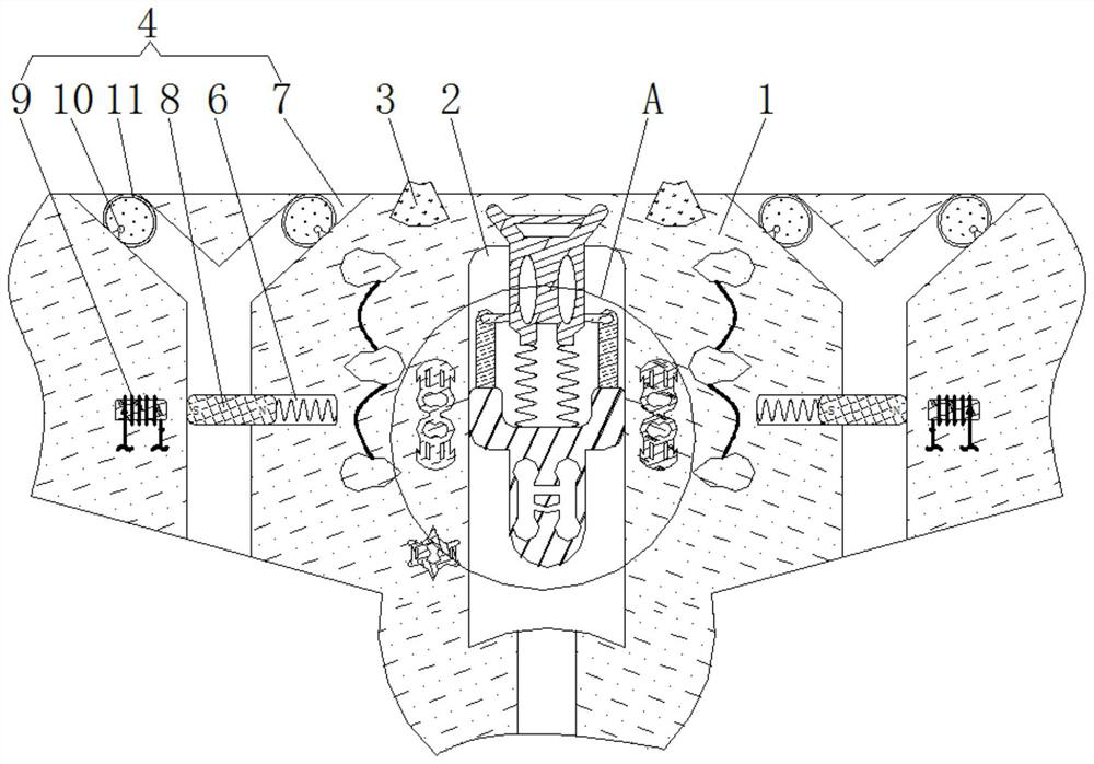
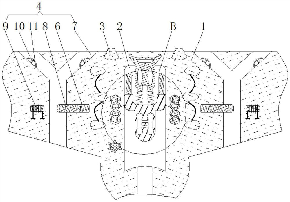
[0025] see figure 1 and image 3 , an injection mold for ultra-precision device processing, including a housing 1, the inner wall of the housing 1 is provided with a chute 2, the inner wall of the housing 1 is fixedly connected with a buzzer 3, and the inner wall of the housing 1 is movably connected with a Decompression mechanism 4;

[0026] The decompression mechanism 4 includes an air outlet groove 7. The inner wall of the housing 1 is provided with a card slot 6. The inner wall of the card slot 6 is elastically connected with a magnetic plate 8. The structure of the magnetic plate 8 is a cuboid structure. The magnetic plate 8 and the inner wall of the card slot 6 Close fit, the number of magnetic plates 8 is the same as the number of winding spiral tubes 9, the magnetic plate 8 plays a closed role, the inner wall of the housing 1 and the outer side close to the magnetic plate 8 are fixedly connected with the winding spiral tubes 9, and the air outlet The inner wall of th...

Embodiment 2

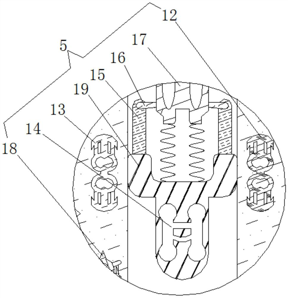
[0028] see Figure 1-4 , an injection mold for ultra-precision device processing, including a housing 1, the inner wall of the housing 1 is provided with a chute 2, the inner wall of the housing 1 is fixedly connected with a buzzer 3, and the inner wall of the housing 1 is movably connected with a A decompression mechanism 4, the inner wall of the housing 1 is movably connected with a trigger mechanism 5;

[0029] The trigger mechanism 5 includes a sliding rheostat 17, the bottom of the sliding rheostat 17 is elastically connected with a slide block 19, the outside of the slide block 19 is fixedly connected with a connecting rod 15, and the inside of the connecting rod 15 is fixedly connected with a metal sheet 16, and the number of the metal sheets 16 is Twice the number of sliding rheostats 17, the metal sheet 16 is electrically connected to the sliding rheostat 17, the sliding rheostat 17 is electrically connected to the piezoresistor 18, the metal sheet 16 plays the role o...

Embodiment 3

[0031] see Figure 1-4 , an injection mold for ultra-precision device processing, including a housing 1, the inner wall of the housing 1 is provided with a chute 2, the inner wall of the housing 1 is fixedly connected with a buzzer 3, and the inner wall of the housing 1 is movably connected with a Decompression mechanism 4;

[0032] The decompression mechanism 4 includes an air outlet groove 7. The inner wall of the housing 1 is provided with a card slot 6. The inner wall of the card slot 6 is elastically connected with a magnetic plate 8. The structure of the magnetic plate 8 is a cuboid structure. The magnetic plate 8 and the inner wall of the card slot 6 Close fit, the number of magnetic plates 8 is the same as the number of winding spiral tubes 9, the magnetic plate 8 plays a closed role, the inner wall of the housing 1 and the outer side close to the magnetic plate 8 are fixedly connected with the winding spiral tubes 9, and the air outlet The inner wall of the groove 7 ...


PUM


Abstract

The invention relates to the technical field of ultra-precision mechanical equipment, and discloses an injection mold for ultra-precision device processing. The injection mold comprises a shell, the inner wall of the shell is provided with a chute, the inner wall of the shell is fixedly connected with a buzzer, the inner wall of the shell is movably connected with a pressure reduction mechanism, and the inner wall of the shell is movably connected with a trigger mechanism. According to the injection mold for ultra-precision device processing, the relative area between a positive plate and a negative plate is reduced through movement of a dielectric medium, so that a piezoresistor connected with the negative plate through a wire is in a working state, and the pressure in the injection mold is prevented from being increased; and more internal stress is prevented from being generated in injection molding liquid injected into the injection mold, deformation of molded injection molding parts is avoided, cracks are prevented from being generated on the surfaces of the injection molding parts, disqualification of injection molding products is avoided, furnace returning and re-making of the injection molding parts are avoided, time and labor are saved, resources are saved, and meanwhile the production efficiency of product injection molding is improved.

Description

technical field [0001] The invention relates to the technical field of ultra-precision mechanical equipment, in particular to an injection mold for processing ultra-precision devices. Background technique [0002] The accuracy of ultra-precision machining is more than one order of magnitude higher than that of traditional precision machining. Relatively speaking, ultra-precision machining has stricter requirements on raw materials, and the raw materials used for processing first need to be shaped by injection molding equipment and then subjected to ultra-precision machining. The complete product can only be obtained through the carving of mechanical equipment. When the existing injection mold is used, the internal pressure will increase. [0003] The existing injection molding device injects the molten injection molding liquid into the injection mold. Due to the increase of the pressure in the injection mold, more internal stress will be generated inside the injection moldin...

Claims


Application Information

Patent Timeline
Patent Type & Authority Applications(China)
IPC IPC(8): B29C45/77B29C45/34
CPCB29C45/77B29C45/34B29C2945/76498B29C2945/76732
Inventor 姚智凡
Owner 南京矿邦机械制造有限公司
Learn More