Sealant filling mechanism based on reciprocating rotation
A technology of reciprocating rotation and sealant, which is applied in the direction of mixers, packaging and mixers with rotating stirring devices, which can solve the problems of increased manual labor, crooked insertion of the mouth of the glue bottle, and increased number of manual operations.
- Summary
- Abstract
- Description
- Claims
- Application Information
AI Technical Summary
Problems solved by technology
Method used
Image

Examples
Embodiment 1
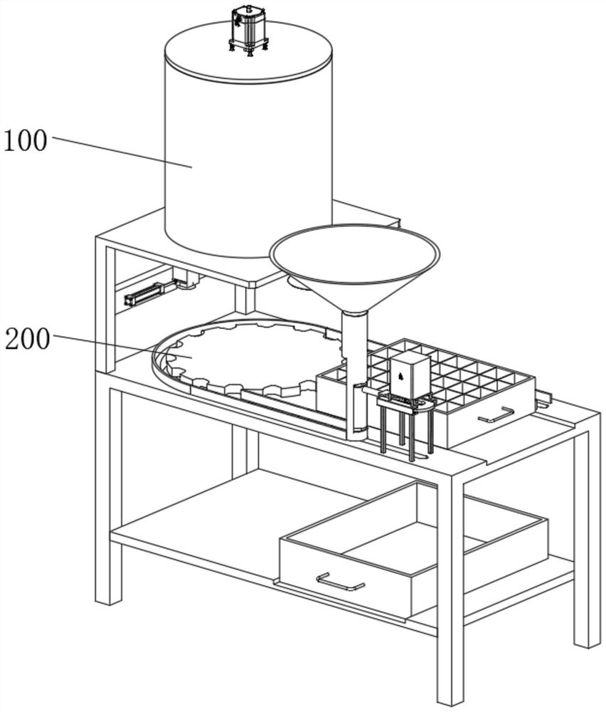
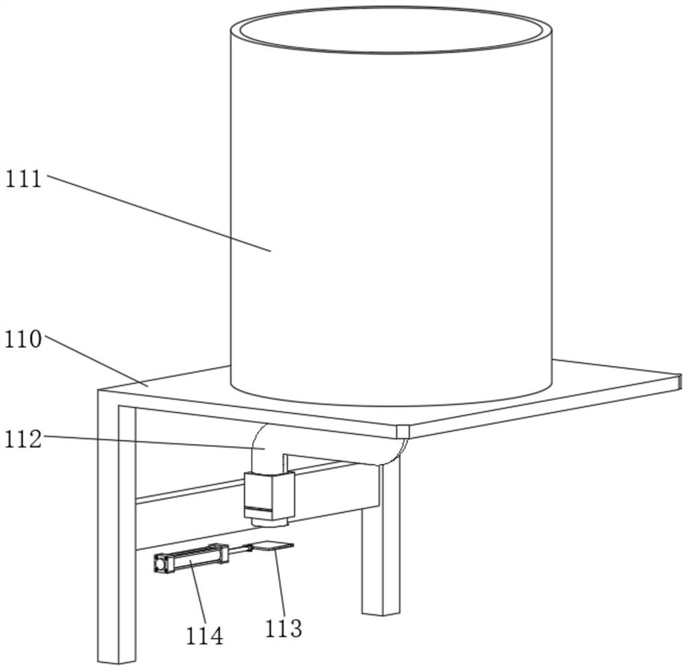
[0051] see Figure 1-Figure 8 As shown, a reciprocating rotary sealant filling mechanism is provided, including a filling device 100 and a mobile device 200 installed below the filling device 100. The filling device 100 includes a support platform 110, and the top of the support platform 110 is installed There is a carrying barrel 111, the bottom of the carrying barrel 111 is connected with a diversion pipe 112, and one end of the diversion pipe 112 is connected with a discharge pipe, and an inserting plate 113 is slidably connected in the discharge pipe, and one end of the inserting plate 113 is fixedly connected with a telescopic rod 114 , the telescopic rod 114 is fixedly connected to one side of the bottom of the support platform 110, and the mobile device 200 at least includes:
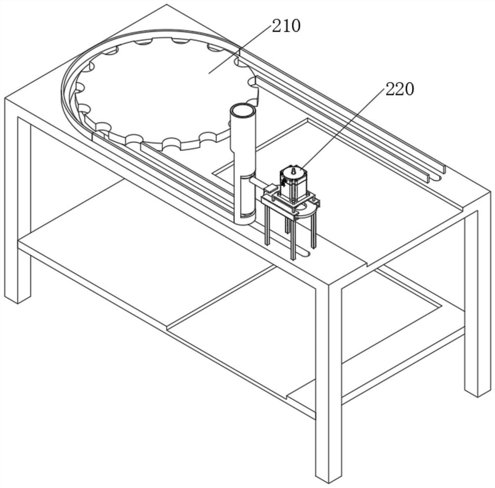
[0052]The flow guide mechanism 210, the flow guide mechanism 210 includes a mounting table 211, one end of the surface of the mounting table 211 is fixedly connected with the support table 110, t...
Embodiment 2
[0060] In order to prevent the solidification phenomenon caused by the long-term placement of the sealant in the carrying bucket 111, the following improvements are made on the basis of implementation 1:
[0061] see Figure 9 As shown, wherein, the top of the carrying bucket 111 is connected with a bucket cover 120, the top of the bucket cover 120 is fixedly connected with a first motor 121, the output shaft of the first motor 121 passes through the bucket cover 120 and is fixedly connected with a stirring shaft 122, stirring The outer wall of the shaft 122 is fixedly connected with a stirring rod, and the sealant is stirred by the provided stirring shaft 122 so that the sealant does not solidify.
[0062] Further, in order to reduce the vibration generated when the first motor 121 is running, the bottom of the first motor 121 is fixedly connected with a slide bar 130, and the outer wall of the slide bar 130 is slidably connected with a slide tube 131, and the slide tube 131 ...
Embodiment 3
[0064] In order to store the plastic bottles, the following improvements are made on the basis of implementation 1:
[0065] see Figure 11 As shown, wherein, the bottom of the mounting table 211 is fixedly connected with a bottom plate 217, and the surface of the bottom plate 217 and the surface of the mounting table 211 are all provided with a mounting groove 218, and a storage box 140 is arranged in the mounting groove 218, and the storage box 140 at the bottom is not placed. For the glue bottle, the storage box 140 on the top places the glue bottle that has been filled with glue, and the glue bottle is stored by the storage box 140 provided so that the glue bottle will not move arbitrarily.
[0066] In addition, in order to prevent the plastic bottles filled with glue in the storage box 140 from being tilted, several isolation plates 141 are arranged in the storage box 140. The plurality of isolation plates 141 are cross-connected, and storage grooves are formed between th...
PUM
 Abstract
Description
Claims
Application Information
 - R&D
- Intellectual Property
- Life Sciences
- Materials
- Tech Scout
- Unparalleled Data Quality
- Higher Quality Content
- 60% Fewer Hallucinations
Browse by: Latest US Patents, China's latest patents, Technical Efficacy Thesaurus, Application Domain, Technology Topic, Popular Technical Reports.
© 2025 PatSnap. All rights reserved.Legal|Privacy policy|Modern Slavery Act Transparency Statement|Sitemap|About US| Contact US: help@patsnap.com