Mask plate with multi-layer structure

A multi-layer structure and mask technology, applied in coating, metal material coating process, ion implantation plating, etc., can solve problems such as sagging, fragile mask structure, shadow, etc., to reduce costs, save materials, Reduce the effect of shadow effects

Pending Publication Date: 2021-07-30
睿馨(珠海)投资发展有限公司
View PDF2 Cites 0 Cited by
  • Summary
  • Abstract
  • Description
  • Claims
  • Application Information

AI Technical Summary

Problems solved by technology

[0004] The invention provides a mask plate with a multi-layer structure to solve the shadow problem in the deposition process in the prior art
[0005] The present invention also solves the problem of weak and sagging of the existing mask structure

Method used


Image

  • Mask plate with multi-layer structure
  • Mask plate with multi-layer structure
  • Mask plate with multi-layer structure

Examples


Embodiment 1

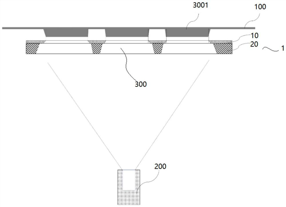
[0027] see figure 1 As shown, a mask plate 1 with a multi-layer structure, the mask plate 1 includes two layers, respectively the first mask layer 10 and the second mask layer 20, the mask plate 1 is provided with a plurality of openings 30. The first mask layer 10 is an extremely thin metal sheet located closest to the substrate 100 , and the opening and pattern of the first mask layer 10 determine the pattern on the silicon substrate 100 to be deposited. Below the first mask layer 10 is a second mask layer 20 . In order to solve the shadow area problem, the opening of the second mask layer 20 is larger than the opening of the first mask layer 10, so that in the process of depositing the organic luminescent material, since the cross section of the first mask layer 10 closest to the substrate 100 is smaller than The cross-section of the second mask layer 20 greatly reduces shadows deposited on the substrate 100 . With such a structure, the second mask layer 20 can be made ...

Embodiment 2

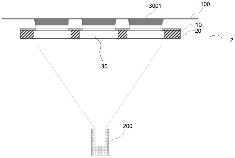
[0031] see figure 2 As shown, a mask plate 2 with a multi-layer structure, the opening cross section of the second mask layer 20 and the opening cross section of the first mask layer 10 form a stepped shape, and the rest is the same as that of Embodiment 1. This kind of structure makes the evaporation material of the organic light-emitting material have a greater flux to reach the substrate without causing waste of materials. At the same time, because it is closer to the deposited silicon substrate 100, the shadow area of ​​the sub-pixel 3001' being deposited will be reduced.

[0032] The beneficial effects that the present invention has are:

[0033] (1) The mask plate of the present invention adopts the design that the entrance of the opening is larger than the exit, which can effectively reduce the shadow effect of the evaporation material;

[0034] (2) The second mask layer can be made thicker due to the opening design of the mask plate, which can effectively support th...


PUM

PropertyMeasurementUnit
Thicknessaaaaaaaaaa
Thicknessaaaaaaaaaa

Abstract

The invention relates to a mask plate with a multi-layer structure. The mask plate comprises at least two layers and is provided with at least one opening; the distance between the first mask layer and a substrate is less than that between the second mask layer and the substrate; the opening cross section of the first mask layer is smaller than that of the second mask layer; and thus, an evaporation material enters the first mask layer through the second mask layer and is finally deposited on the substrate. The mask plate has the following beneficial effects: the design that an inlet of the opening is larger than an outlet is adopted, so that the shadow effect of the evaporation material can be effectively reduced; and due to the design for the opening, the second mask layer can be made to be thicker, and the first mask layer can be effectively supported, so that the problems of vulnerability and sagging of an existing mask plate can be solved.

Description

technical field [0001] The invention relates to the technical field of material mask patterned deposition, in particular to a mask plate with a multi-layer structure. Background technique [0002] Modern technology and applications require organic light-emitting microdisplays with higher and higher resolutions to display smaller and smaller sub-pixel sizes. The shortest size is already less than 3.5 microns, rapidly approaching 2 microns, and even the distance between sub-pixels is less than 1 micron. . In the organic light-emitting microdisplay evaporation process, the structure of the ultra-high resolution mask is used to pattern a single sub-pixel, so that the display can realize RGB independent pixel light-emitting display. Due to the requirement on the precision of the patterning process, the structure of the mask needs to use an extremely thin mask structure. The structure of such a mask is very fragile and may sag, making its use and storage in the evaporation proce...

Claims


Application Information

Patent Timeline
IPC IPC(8): C23C14/04C23C14/24H01L51/56
CPCC23C14/042C23C14/24H10K71/166H10K71/00
Inventor 茆胜
Owner 睿馨(珠海)投资发展有限公司
Why Eureka
Try Eureka