Low-profile solar tracking module

Inactive Publication Date: 2009-10-08
3T SOLAR
View PDF3 Cites 59 Cited by
  • Summary
  • Abstract
  • Description
  • Claims
  • Application Information

AI Technical Summary

Benefits of technology

[0014]An apparatus for distribution of light across a target area has at least one non-shadowing lens. The non-shadowing lens has a plurality of prisms wherein each prism provides an approximately uniform distribution of light across a defined area of the target area to reduce a shadowing effect.
[0016]A method of converting solar energy to electrical energy comprising: automatically progressively and collectively turning and tilting an array of non-shadowing lenses to maintain an essentially perpendicular relationship between rays of sunlight and the non-shadowing lenses, each of the non-shadowing lenses having a plurality of prisms wherein each prism provides an approximately uniform distribution of light across a target area to reduce a shadowing effect on a solar cell positioned below at least one of the non-shadowing lenses.

Problems solved by technology

Because of this requirement, the orientation of PV panel installations may be forced to be less than optimal, thereby further decreasing the rate of return of the PV panel.
Current two-axis solar tracking systems are typically large.
The large, elevated panel areas are potentially exposed to high wind loads.
As a result, all the components of these systems must be quite robust, and therefore expensive.
This type of installation may work well for industrial power generation sites, but they are unwieldy for home or most commercial installations.
Thus, current two-axis solar tracking systems may be too large and bulky to satisfy these requirements.
When used for energy collection, the current art of Fresnel lenses has a significant weakness—any shadows cast upon them translate directly to the target area.
Non-uniform light on a photovoltaic target cell can significantly reduce its power output.
This, in turn, can reduce the power output for an array of cells that is serially wired to the shadowed cell.
At high light concentrations of 20 to 2000 suns, uneven illumination also can cause thermal stresses that result in cracking and premature failure of the target cells.
Economic and practical realities limit the roof or land space allotted to a single solar collector.
Some grouping of collectors is required in most installations, and concomitant shadowing usually occurs.
When one tracker begins to shade another, the trackers are often turned away from the sun due to this shadowing issue.
Despite much discussion about solar power and its advantages, fixed panels are relatively inefficient.
Existing two-axis tracking systems improve efficiency, but remain too heavy, expensive, and visible for most installations.

Method used


Image

  • Low-profile solar tracking module
  • Low-profile solar tracking module
  • Low-profile solar tracking module

Examples


Embodiment Construction

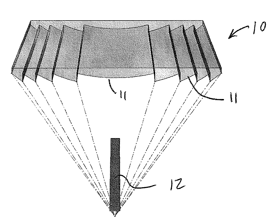
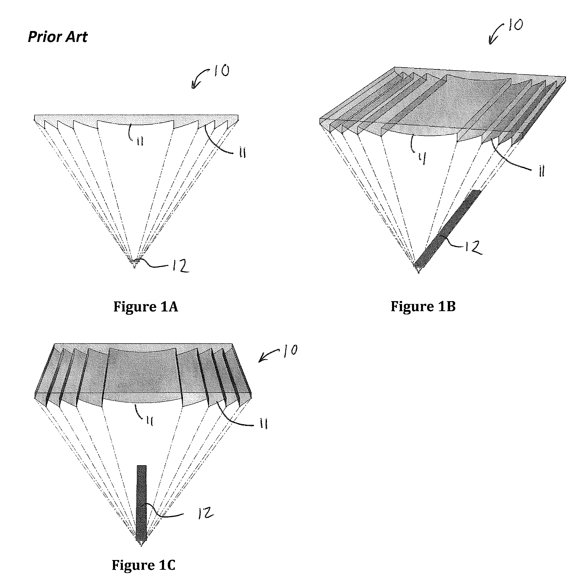
[0045]Referring now to FIGS. 1A-1C, a prior art single focal point linear Fresnel lens 10 is shown. The Fresnel lens 10 has a surface consisting of a series of simple lens sections 11 so that a thin lens with a short focal length and large diameters is possible. In the Fresnel lens 10, the surfaces of these lens sections 11 are designed to refract the light by collapsing the surface curvature of a conventional convex lens into a thin planar or curved sheet. As shown in FIG. 1, the surfaces of the prism side of the lens sections 11 approximate the curvature of a spherical or aspherical conventional lens. When looking at the surface geometry of adjacent lens sections 11, the end slope of one lens section 11 and the beginning slope of the next lens section 11 is parallel or nearly parallel.

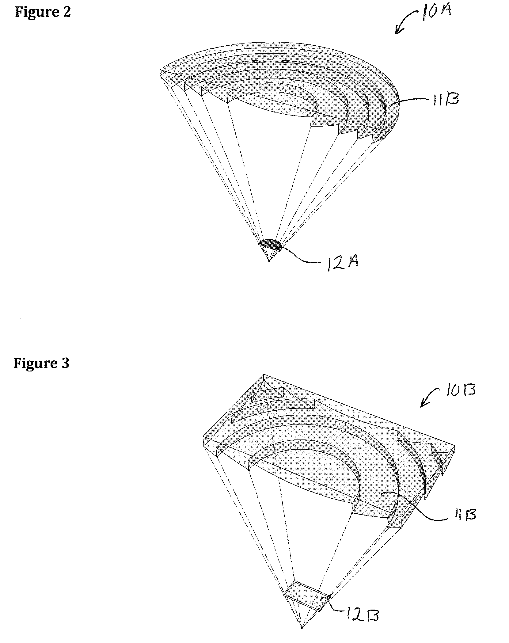
[0046]Referring to FIG. 2, one embodiment of a prior art Fresnel lens 10A is shown. In this embodiment, the Fresnel lens 10A is a circular, or 3-Dimensional, lens. The Fresnel lens 10A is used for il...


PUM


Abstract

An apparatus for distribution of light across a target area has at least one non-shadowing lens. The non-shadowing lens has a plurality of prisms wherein each prism provides an approximately uniform distribution of light across a defined area of the target area to reduce a shadowing effect. The apparatus may further have a tracking mechanism attached to the at least one non-shadowing lens for orienting the at least one non-shadowing lens towards a source of the light.

Description

FIELD OF THE INVENTION[0001]The present application is related to U.S. Provisional Application having Ser. No. 61 / 123,108, filed Apr. 5, 2008 and entitled, “LOW-PROFILE SOLAR TRACKING MODULE”. The present patent application claims the benefit under 35 U.S.C. §119(e).FIELD OF THE INVENTION[0002]This invention relates to solar energy and, more specifically, to a low-profile solar tracking apparatus that utilizes a non-shadowing lens for concentrating solar radiation and which provides a uniform light distribution across a target area of the solar panel.BACKGROUND OF THE INVENTION[0003]Traditional solar photovoltaic (PV) panels must be angled high in order for them to optimally perform. The typical recommendation for a fixed PV panel installation is to mount the PV panel equivalent to the latitude, which in the United States typically ranges from 30 to 50 degrees from horizontal. Fixed panels should also face the location's maximum solar elevation, which is South for the Northern Hemis...

Claims


Application Information

Patent Timeline
IPC IPC(8): H01L31/052
CPCF24J2/085F24J2/5427F24J2002/5468G02B3/08H01L31/0543Y02E10/43Y02E10/47Y02E10/52G02B27/0927F24S30/458F24S23/31F24S2030/136
Inventor THORLEY, BRENT PERRYTHORLEY, GREGORY DAVIDTHORLEY, DAVID HARRIS
Owner 3T SOLAR
Why Eureka
Try Eureka