
Reinforced wind-clamping-resistant system of metal roof board

A metal roof and panel technology, which is applied in the direction of roof, roof covering, roof using flat/curved panels, etc., can solve the problem of low wind load bearing capacity of connection nodes, weak wind resistance performance, and resistance to wind pressure of connection nodes. Weak wind resistance and other problems, to reduce the possibility of local wind wind damage, improve the wind load bearing capacity, and enhance the wind resistance performance.

Active Publication Date: 2021-07-30
ARCHITECTURAL DESIGN RES INST OF GUANGDONG PROVINCE
View PDF8 Cites 2 Cited by
  • Summary
  • Abstract
  • Description
  • Claims
  • Application Information

AI Technical Summary

Problems solved by technology

[0003] However, the above-mentioned metal roof panel system has the following defects: the ears of adjacent U-shaped roof panels are connected by mechanical occlusal. Especially in the coastal strong typhoon area, due to the weak wind resistance performance of the connecting nodes, the damage of the metal roof panel due to the wind exposure occurs from time to time

Method used


Image

  • Reinforced wind-clamping-resistant system of metal roof board
  • Reinforced wind-clamping-resistant system of metal roof board
  • Reinforced wind-clamping-resistant system of metal roof board

Examples


Embodiment 1

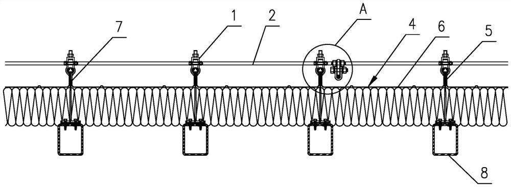
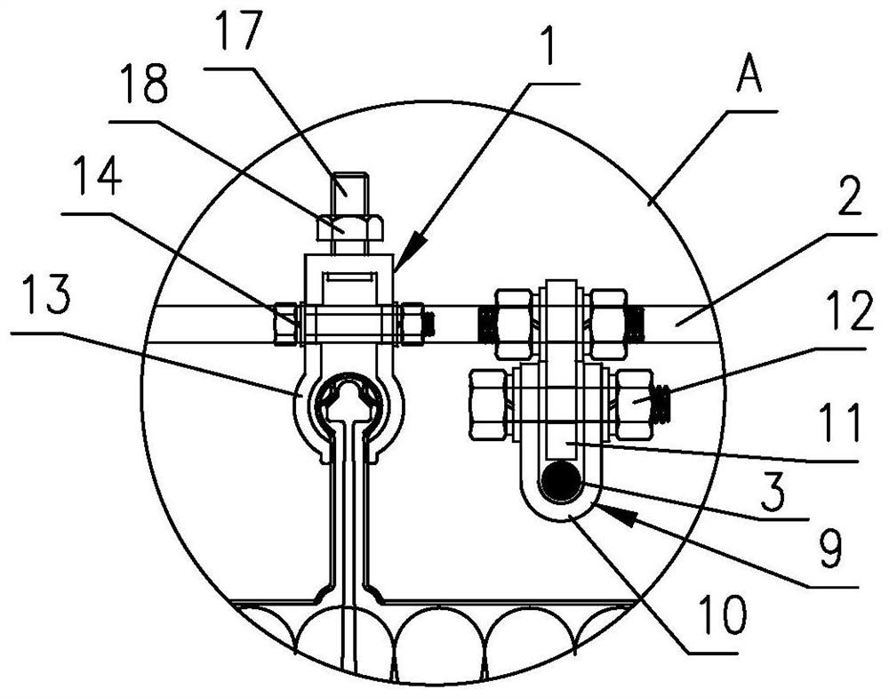
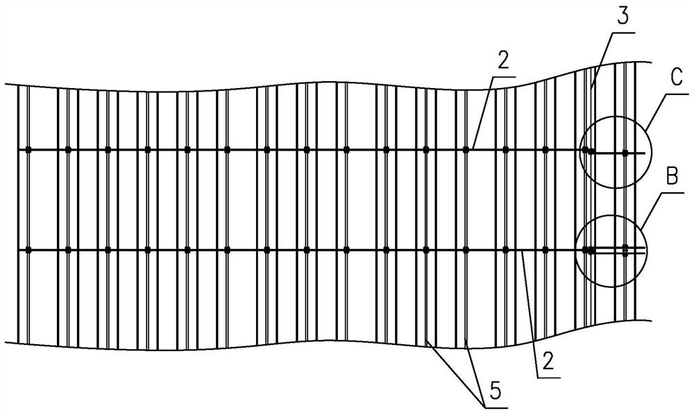
[0029] Such as Figure 1~5 As shown, it is a metal roof panel reinforced wind-resistant clip system of the present invention, which includes connecting units. In this embodiment, each group of connecting units includes several groups of wind-resistant clips 1 and connecting rods 2, and several groups of connecting units A wind-resistant clamp 1 is sequentially clamped on each plate rib 5 of the metal roof panel 4, and the plate rib 5 is the ear of the adjacent U-shaped roof panel 6, which is mechanically snapped on the plum blossom head at the upper end of the T-shaped support 7. formed. The connecting rod 2 is a stainless steel rod, which spans the metal roof panel 4 and passes through each wind-resistant clip 1 . A number of prestressed cables 3 are provided along the longitudinal extension of the metal roof panel 4, each prestressed cable 3 is connected to the connecting rod 2, and the prestressed cables 3 are parallel to the plate ribs 5, and the prestressed cables 3 Bot...

Embodiment 2

[0036] Such as Figure 6 As shown, the difference between this embodiment and Embodiment 1 is that a keel 15 and a decorative plate 16 laid on the keel 15 are arranged above the metal roof panel 4, and the decorative plate 16 is fixed on the keel 15 by angle steel and bolts , the anti-wind clip 1 is connected with the keel 15. Specifically, a connecting structure for connecting the keel 15 is provided at the upper end of the wind-resistant clamp 1, see figure 2 , the connection structure is a hole, which is used to cooperate with the fastener 17 and the nut 18 to be fixed on the fixed plate 19 connecting the keel 15, the upper part of the fixed plate 19 is fixed on the keel 15 by bolts, and its lower end has a horizontal flange, fastening Part 17 passes through the folded edge and is then fixed by nuts to connect the wind-resistant clip with the keel. Layer decorative panels can improve the aesthetics of building roofs.

[0037] In other embodiments, each group of connecti...


PUM


Abstract

The invention discloses a reinforced wind-clamping-resistant system of a metal roof board. The system comprises a plurality of connecting units; each connecting unit comprises wind-resistant clamps and connecting rods / prestress inhaul cables; the multiple wind-resistant clamps of each connecting unit are sequentially clamped on each plate rib of the metal roof board; the connecting rods / prestress inhaul cables stretch across the metal roof board and penetrate through the wind-resistant clamps; a plurality of connecting rods / prestress inhaul cables are arranged in the longitudinal direction of the metal roof board in an extending mode; and each connecting rod / prestress inhaul cable is connected with the connecting rods / prestress inhaul cables of the connecting units. According to the reinforced wind-clamping-resistant system of the metal roof board, the wind-resistant clamps can firmly clamp the plate ribs, and the wind uplift resistance of a plate rib mechanical occlusion joint is enhanced; when the connecting rods / prestressed inhaul cables extending in the longitudinal direction of the metal roof board deform along with wind suction of the roof board, the deformation level of the roof board can be limited; and the prestress inhaul cables / connecting rods of the connecting units enhance the integrity of the roof wind-clamping-resistant system, the wind load bearing capacity of the roof board is improved, and the possibility of local wind uplift damage is reduced.

Description

technical field [0001] The invention belongs to the wind-resistant technology of civil engineering roofs, in particular to a metal roof plate reinforced wind-resistant clip system. Background technique [0002] In recent years, the metal roof panel system has been widely used in long-span steel structures such as terminal buildings, stadiums, and exhibition buildings due to its advantages of good waterproof effect, partial elimination of temperature stress, and simple construction. The metal roof panel system usually includes several U-shaped roof panels and T-shaped supports. The ears of adjacent U-shaped roof panels are mechanically snapped and fastened to the plum blossom head at the upper end of the T-shaped supports to form the ribs of the roof panel. Several U-shaped roof panels are connected into one body, and the lower end of the T-shaped support is fixed on the supporting purlin under the roof panel, and the load is transmitted to the supporting purlin through the T...

Claims


Application Information

Patent Timeline
Patent Type & Authority Applications(China)
IPC IPC(8): E04D3/36
CPCE04D3/36
Inventor 区彤谭坚石煦阳龙秀海林松伟
Owner ARCHITECTURAL DESIGN RES INST OF GUANGDONG PROVINCE
Learn More