A vein projection device

A technology of projection device and vein, which is applied in medical science, using spectrum diagnosis, diagnosis, etc., can solve problems such as the limitation of application range, and achieve the effect of avoiding rigid collision, realizing height adjustment, and avoiding random shaking

Active Publication Date: 2022-07-15
SHENZHEN XINHANGXIANG TECH CO LTD
View PDF7 Cites 0 Cited by
  • Summary
  • Abstract
  • Description
  • Claims
  • Application Information

AI Technical Summary

Problems solved by technology

[0005] However, the existing vein projection device is generally fixedly arranged above the workbench. During use, the patient needs to place his hand directly below the projection device. When performing venipuncture, its scope of application is significantly limited

Method used


Image

  • A vein projection device
  • A vein projection device
  • A vein projection device

Examples


Embodiment 1

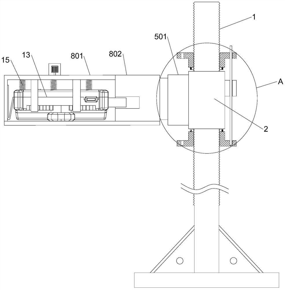
[0038] The vein projection device of the present invention includes a projector body 13, a box 8 for placing the projector body 13, and a positioning column 1. The positioning column 1 is sleeved with a sleeve 2 that can move up and down, and the positioning column 1 is also provided with There is a fixed component 3 for fixing the sleeve 2, a rotating component 5 is arranged between the outer wall of the sleeve 2 and the box body 8, and the rotating component 5 is used to adjust the inclination angle of the box body 8 and the horizontal plane. The box body 8 includes The upper casing 801 and the lower casing 802 are detachable, the bottom wall of the lower casing 802 is provided with an escape hole, and the projector body 13 and the inner side wall of the lower casing 802 are provided with a space for lifting the projector body 13. For the locking assembly 6 for fixing, the lower end of the upper casing 801 is provided with an elastic positioning assembly 9 which is located ou...

Embodiment 2

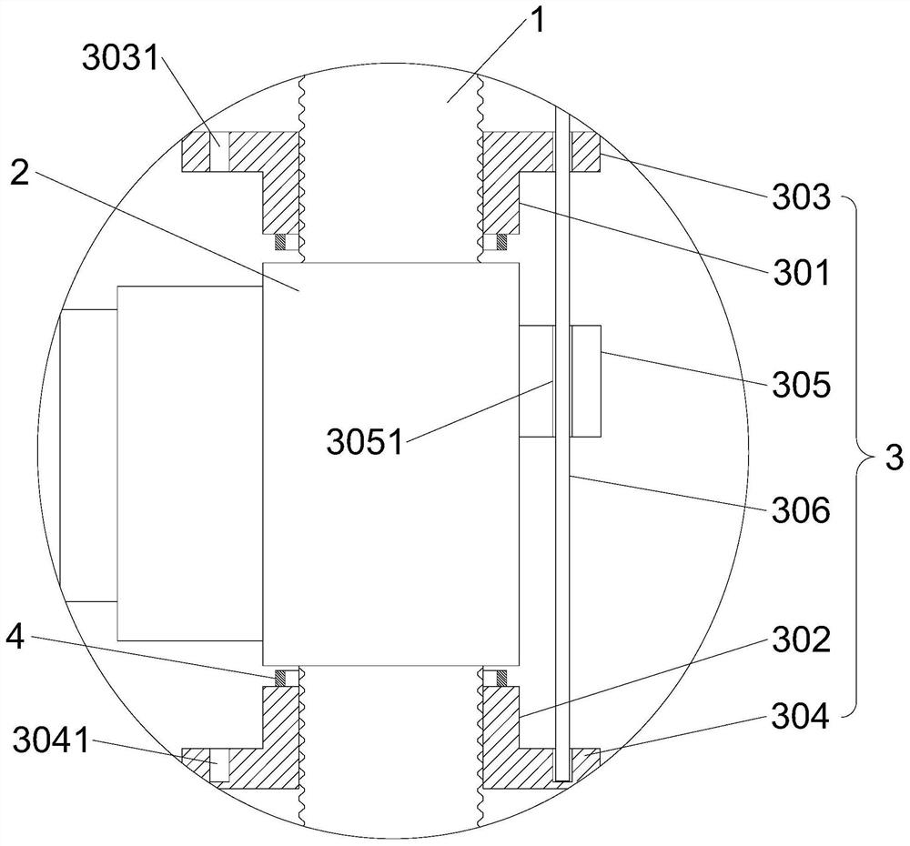
[0041] This embodiment is further optimized on the basis of Embodiment 1 as follows: the fixing assembly 3 includes an upper fixing sleeve 301, a lower fixing sleeve 302, an upper flange 303, a lower flange 304, a fixing rod 306 and a fixing block 305; positioning The outer wall of the column 1 is provided with an external thread, and the upper fixing sleeve 301 and the lower fixing sleeve 302 are both provided with an inner thread that is compatible with the external thread. The flange 303 is arranged on the outer wall of the upper fixing sleeve 301, and the lower flange 304 is arranged on the outer wall of the lower fixing sleeve 302. The upper flange 303 is provided with a plurality of through holes 3031, and all the through holes 3031 are distributed in an annular array. Blind holes 3041 corresponding to the through holes 3031 one-to-one, the fixing block 305 is arranged on the outer wall of the sleeve 2, the fixing block 305 is vertically pierced with a fixing hole 3051 th...

Embodiment 3

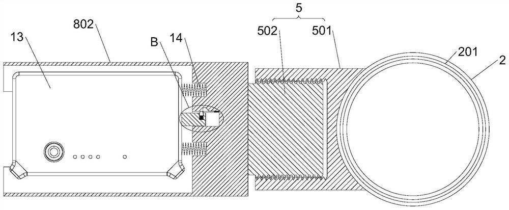
[0044] This embodiment is further optimized on the basis of Embodiment 1 as follows: the rotating assembly 5 includes a rotating cylinder 501 and a rotating column 502, one end of the rotating cylinder 501 is connected with the sleeve 2, and the other end of the rotating cylinder 501 is provided with a One end of the rotating column 502 is connected with the outer wall of the lower casing 802, and the other end of the rotating column 502 is screwed with the inner wall of the rotating groove.

[0045] After the above technical solution is adopted: the rotating assembly 5 is the rotating cylinder 501 and the rotating column 502 that are threadedly matched, that is, by rotating the rotating column 502, the box body 8 can follow the rotating column 502 to adjust the inclination angle relative to the horizontal plane. Any angle, and can keep the angle unchanged.


PUM


Abstract

The invention discloses a vein projection device, which relates to the technical field of vein projection devices. The invention includes a projector body, a box for placing the projector body, and a positioning column. The positioning column is sleeved with a sleeve that can move up and down, and the positioning column is also provided with a fixing component for fixing the sleeve. A rotating assembly is arranged between the outer wall of the sleeve and the box body, and the box body includes a detachable upper shell and a lower shell, the bottom wall of the lower shell is provided with a space hole, and the inside of the projector body and the lower shell A locking component is arranged between the walls, and an elastic positioning component is arranged at the lower end of the upper casing. After the projection device can be placed on the workbench through the auxiliary fixing device, the relative height, the relative inclination angle and the horizontal position of the projection device can be adjusted, and the projection device body can be disassembled for independent use.

Description

technical field [0001] The present invention relates to the technical field of vein projection devices, in particular to a vein projection device. Background technique [0002] In modern medical technology, venipuncture is used to draw out blood, infuse blood, or infuse liquids such as normal saline, but the key to implementing this medical technology is to find the blood vessels of the human body, and then puncture the blood vessels with a needle for subsequent treatment. When targeting different patient populations, a large amount of experience is often required to locate the blood vessel and ensure the probability of successful puncture. When nurses perform puncture operations on some patients with weak subcutaneous veins, the failure rate is extremely high, but by using vein imaging technology to visualize the veins, it can effectively assist nurses to locate the blood vessels, reduce the need for experience accumulation, and improve the success of puncture. The probabi...

Claims


Application Information

Patent Timeline
Patent Type & Authority Patents(China)
IPC IPC(8): A61B5/00F16M11/10F16M11/18F16M11/04
CPCF16M11/04F16M11/046F16M11/18F16M11/10A61B5/489A61B5/0064A61B5/0075F16M2200/02
Inventor 王凯
Owner SHENZHEN XINHANGXIANG TECH CO LTD
Why Eureka
Try Eureka