Laser measuring device for deflection of leveling oil cylinder

A laser measurement and leveling oil cylinder technology, applied in the direction of measuring devices, optical devices, instruments, etc., can solve the problems of limited test accuracy, sinking of the vehicle body, and difficulty in ensuring the accuracy of the test structure, so as to reduce the labor intensity of personnel, The effect of improving detection accuracy

Inactive Publication Date: 2021-07-30
BEIJING MECHANICAL EQUIP INST
View PDF5 Cites 2 Cited by
  • Summary
  • Abstract
  • Description
  • Claims
  • Application Information

AI Technical Summary

Problems solved by technology

[0003] In the test of the sinking amount of the leveling cylinder of the equipped vehicle, the instrument used to detect the holding capacity of the leveling cylinder is mainly a steel tape or a dial indicator. The steel tape is attached to the outer cylinder of the leveling cylinder to measure the ground distance, or a dial The sub-meter is directly adsorbed on the surface of the inner cylinder of the leveling oil cylinder, and is pushed against the lower edge of the outer cylinder. Manual measurement is used to read and record the value, and the measured value is compared at a certain time interval, and the change of the sinking amount is manually calculated. This measurement method It is easily affected by multiple factors such as product working conditions, environmental factors of the test site, and personnel operations. The test accuracy is limited, and the obtained data is not conducive to effective analysis of product performance. It is difficult to ensure the accuracy of the test structure, especially during the test process. The body needs to be kept under load for 12h to 48h. The vehicle is prone to the failure of the oil cylinder, causing the risk of sinking or even overturning the vehicle body. Therefore, personnel need to be on duty for a long time, and manual tracking and recording are required for multiple comparison calculations, which is labor-intensive. Big

Method used


Image

  • Laser measuring device for deflection of leveling oil cylinder
  • Laser measuring device for deflection of leveling oil cylinder
  • Laser measuring device for deflection of leveling oil cylinder

Examples


Embodiment Construction

[0019] In order to make the object, technical solution and advantages of the present invention clearer, the present invention will be further described in detail below in conjunction with the accompanying drawings and embodiments. It should be emphasized that the specific embodiments described here are only used to better illustrate the present invention, and are some, not all, embodiments of the present invention, so they are not used to limit the present invention. In addition, the technical features involved in the embodiments of the present invention described below may be combined with each other as long as they do not conflict with each other.

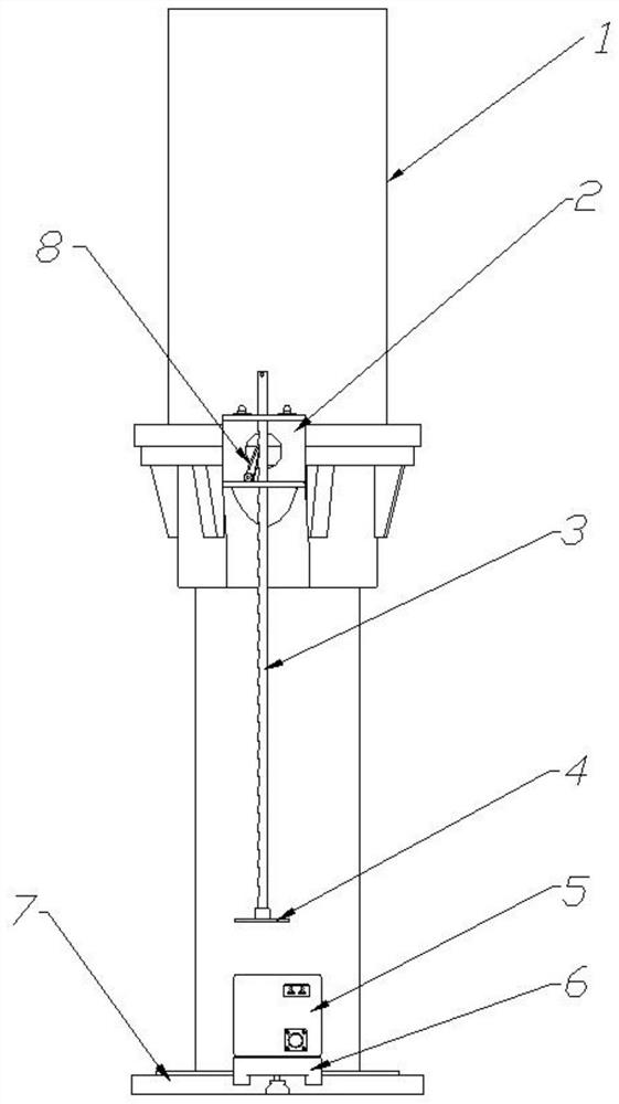
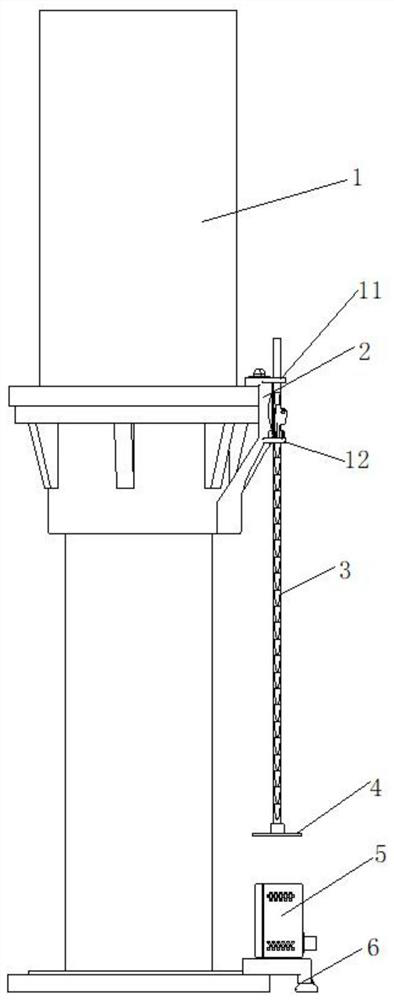
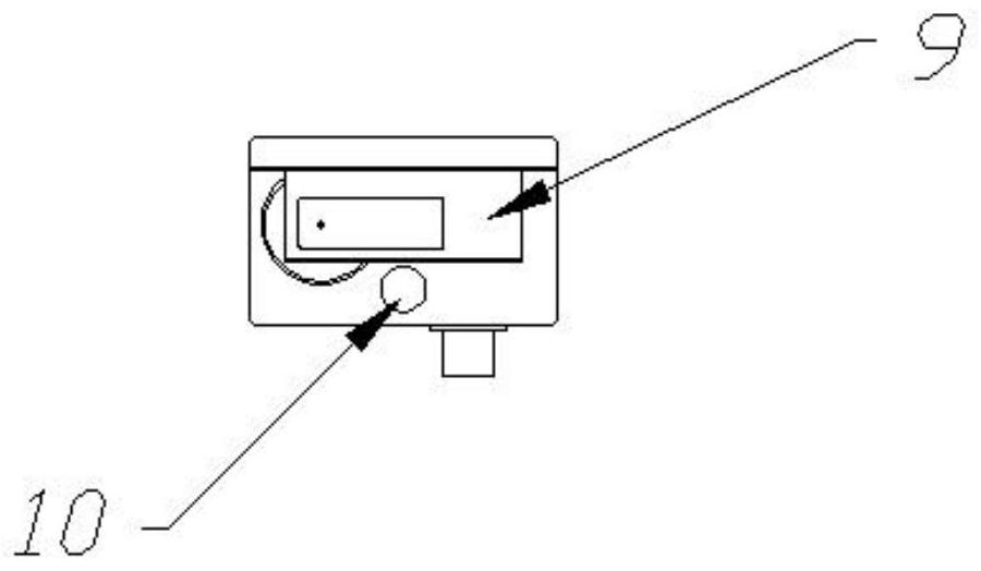
[0020] see in conjunction Figure 1-4 As shown, according to the embodiment of the present invention, the laser measuring device for leveling the sinking amount of the oil cylinder includes an upper fixing assembly 2, a lifting mechanism, a reflector and a laser displacement sensor 9, and the upper fixing assembly 2 is installed ...


PUM


Abstract

The invention discloses a laser measuring device for the deflection of a leveling oil cylinder. The laser measuring device for the deflection of the leveling oil cylinder comprises an upper fixing assembly, a lifting mechanism, a reflector and a laser displacement sensor, wherein the upper fixing assembly is installed on a cylinder barrel of the leveling oil cylinder, and the lifting mechanism is installed on the upper fixing assembly and can move up and down relative to the upper fixing assembly; the reflector is installed at the end, close to the laser displacement sensor, of the lifting mechanism, and the laser displacement sensor detects the deflection of the leveling oil cylinder according to light reflected by the reflector. The laser measuring device for the deflection of the leveling oil cylinder can monitor the deflection of the leveling oil cylinder, the labor intensity of workers is relieved, and the detection precision is improved.

Description

technical field [0001] The invention belongs to the technical field of leveling devices, and in particular relates to a laser measuring device for leveling the sinking amount of an oil cylinder. Background technique [0002] In order to provide a good launch platform for the equipped vehicle, it is necessary to perform leveling operations on the vehicle body and keep it in a horizontal position. The prior art adopts hydraulic leveling oil cylinder control technology to realize vehicle body leveling. Because of its high control precision, easy design, maintenance and use, it is widely used in equipment vehicles. The sinking amount of the hydraulic leveling cylinder of the vehicle is an important indicator reflecting the static holding performance of the leveling cylinder. Before delivery, each equipped vehicle needs to check the holding performance of the hydraulic leveling cylinder to confirm that it meets the requirements of no-load or full-load holding for a certain period...

Claims


Application Information

Patent Timeline
Patent Type & Authority Applications(China)
IPC IPC(8): G01B11/02
CPCG01B11/02
Inventor 刘祖华石玉超
Owner BEIJING MECHANICAL EQUIP INST
Why Eureka
Try Eureka