A supersonic plane cascade flow field start-up and uniformity adjustment device

A technology for regulating devices and cascade flow, which is applied in measuring devices, engine tests, jet engine tests, etc., can solve the problems of great difference in model blockage, great difference in flow conditions between head and tail blades, and limitations, etc. Achieve the effect of eliminating reflection problems, eliminating shock wave reflection problems, and achieving uniformity

Active Publication Date: 2022-07-01
中国空气动力研究与发展中心空天技术研究所
View PDF0 Cites 0 Cited by
  • Summary
  • Abstract
  • Description
  • Claims
  • Application Information

AI Technical Summary

Problems solved by technology

[0004] At present, due to the relative scarcity of supersonic planar cascade test platforms, the development of supersonic compressor planar cascade tests with incoming flow is limited, and it is even more difficult to effectively adjust the supersonic incoming flow conditions.
In fact, due to the very small installation angle of the supersonic compressor cascade test piece, after entering the test section area, the blockage degree of the model at the same axial position is very different; at the same time, due to the shock wave system in front of the cascade, the / oblique shock wave, there will be shock loss and deflection of airflow angle, which will directly lead to a great difference in the flow conditions of the front and rear blades of the test piece; because the supersonic flow field is extremely sensitive to the flow state of the upper and lower discharge holes of the test piece, Whether the shock wave system of the discharge channel is in the channel or in the state of the bow shock wave directly affects the shock wave system structure of the first blade in the test section and affects the subsequent series of blades; whether there is reflection at the front end of the first blade affects most of the blades. Channel start-up problem

Method used


Image

  • A supersonic plane cascade flow field start-up and uniformity adjustment device
  • A supersonic plane cascade flow field start-up and uniformity adjustment device
  • A supersonic plane cascade flow field start-up and uniformity adjustment device

Examples


Embodiment Construction

[0045] The present invention will be described in detail below with reference to the accompanying drawings and embodiments.

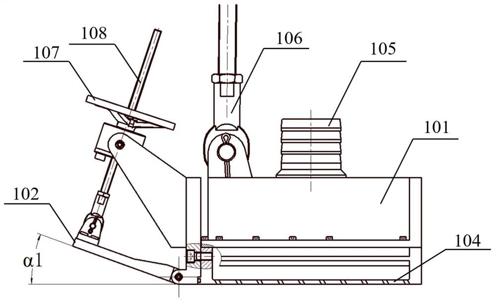
[0046] like figure 1 As shown, with the flow from the cascade wind tunnel as the front, the supersonic plane cascade flow field start-up and uniformity adjustment device of the present invention includes an upper suction assembly 1 installed above the first blade of the cascade test model, an upper suction assembly 1 An upper tail plate 102 with a fixed front end and a suspended rear end is installed at the rear of the blade, and an upper baffle 103 with a fixed front end and a suspended rear end is installed behind the bow blade; it also includes a lower suction assembly 2 installed under the tail blade of the cascade test model. , a lower tail plate 202 with a fixed front end and a suspended rear end is installed behind the lower suction assembly 2, and a lower baffle 203 with a fixed front end and a suspended rear end is installed behind the tail bla...


PUM


Abstract

The invention discloses a supersonic plane blade cascade flow field starting and uniformity adjusting device. The adjusting device takes the flow from the cascade wind tunnel as the front, and includes an upper suction assembly installed above the leading blade of the cascade test model. Behind the upper suction assembly is an upper tail plate with a fixed front end and a suspended An upper baffle with a fixed front end and a suspended rear end is installed at the rear; it also includes a lower suction assembly installed under the tail blade of the cascade test model, and a lower tail plate with a fixed front end and a suspended rear end is installed behind the lower suction assembly. A lower baffle with a fixed front end and a suspended rear end is installed behind the tail blade. The adjusting device can stabilize the mass flow of the discharge channel in the suction test section, provide a local low-pressure environment to stabilize the shock wave structure of the discharge channel, regulate the pressure distribution in front of the grid, and realize the start-up and uniformity adjustment of the supersonic flow field.

Description

technical field [0001] The invention belongs to the field of aero-engine integrated research and test equipment, and in particular relates to a supersonic plane blade cascade flow field start-up and uniformity adjustment device. Background technique [0002] The replacement and development of aero-engines has continuously promoted the progress of aero-turbine design technology. The relative Mach number of the blade tip of the fan and compressor rotor blades and the Mach number of the turbine blade outlet have exceeded the speed of sound, and some aerodynamic design schemes have reached the Mach number of 1.5 or more. The appearance of supersonic shock waves has introduced a big problem to the aerodynamic design of components. It is not only necessary to make full use of the supercharging effect of the shock waves to effectively increase the pressure, but also to effectively organize the shock wave structure to prevent the shock waves from attaching to the blade boundary layer...

Claims


Application Information

Patent Timeline
Patent Type & Authority Patents(China)
IPC IPC(8): G01M9/04G01M15/02G01M15/14
CPCG01M9/04G01M15/02G01M15/14
Inventor 魏巍马护生任思源时培杰李学臣宗有海陈峰黄康叶敏江辉李聪谭锡容
Owner 中国空气动力研究与发展中心空天技术研究所
Why Eureka
Try Eureka