
Fluxgate current sensor sampling resistor ripple current compensation method

A technology of current sensor and sampling resistor, applied in the direction of measuring current/voltage, measuring current only, voltage/current isolation, etc., can solve the problems of high-precision measurement of current, and achieve the effect of reducing ripple noise and improving stability

Pending Publication Date: 2021-07-30
SHANGHAI TECH UNIV +1
View PDF0 Cites 1 Cited by
  • Summary
  • Abstract
  • Description
  • Claims
  • Application Information

AI Technical Summary

Problems solved by technology

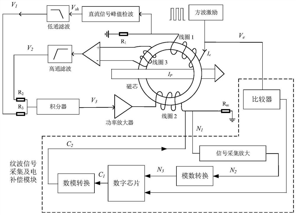
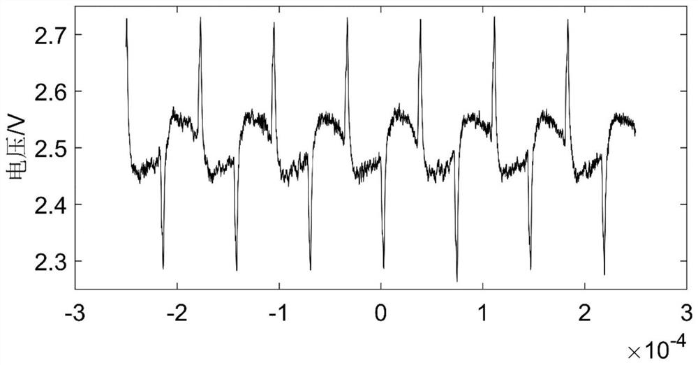
[0005] The technical problem to be solved by the present invention is: the excitation square wave of the current fluxgate current sensor utilizing nonlinear magnetic material characteristics will introduce the excitation signal frequency and the ripple noise of the frequency multiplication of the excitation signal frequency in the actual measurement results, which will affect the current high-precision measurement of

Method used


Image

  • Fluxgate current sensor sampling resistor ripple current compensation method
  • Fluxgate current sensor sampling resistor ripple current compensation method
  • Fluxgate current sensor sampling resistor ripple current compensation method

Examples


Embodiment Construction

[0039] Below in conjunction with specific embodiment, further illustrate the present invention. It should be understood that these examples are only used to illustrate the present invention and are not intended to limit the scope of the present invention. In addition, it should be understood that after reading the teachings of the present invention, those skilled in the art can make various changes or modifications to the present invention, and these equivalent forms also fall within the scope defined by the appended claims of the present application.

[0040] A secondary side ripple current compensation method of a fluxgate current sensor disclosed in this embodiment specifically includes the following steps:

[0041] Step 1. Use an analog amplifier circuit to amplify the ripple noise introduced by the excitation signal in the fluxgate current sensor circuit.

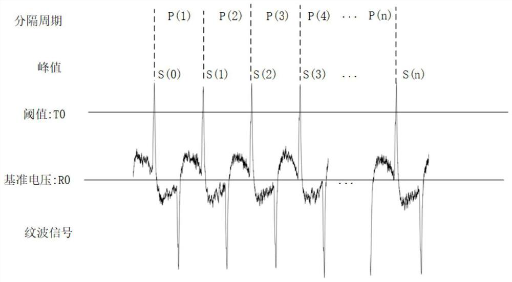
[0042] Step 2, collecting the amplified ripple noise of several acquisition periods, and then performing digital pr...


PUM


Abstract

The invention discloses a fluxgate current sensor sampling resistor ripple current compensation method, which is characterized by comprising the following steps of in a current acquisition period, acquiring a ripple noise signal introduced by an excitation signal given by a square wave module generated by self-oscillation in a fluxgate current sensor circuit, carrying out amplification processing on the ripple noise signal by utilizing an analog amplification circuit, obtaining amplified ripple noise signals of a plurality of acquisition periods, performing digital processing on the collected amplified ripple noise signals of the plurality of acquisition periods, and converting the amplified ripple noise signals into noise offset signals, and inputting the noise offset signal into the fluxgate current sensor circuit through a digital-to-analog conversion module, and using the noise offset signal to offset the ripple noise of the fluxgate current sensor circuit. According to a result obtained by testing an existing model machine, the ripple noise in the current sensor can be remarkably reduced through the ripple noise counteracting function, and good stability is shown.

Description

technical field [0001] The invention relates to an open-loop electrical compensation and suppression method for modulation ripple of a fluxgate high-current sensor. Background technique [0002] Current sensors fall into two main categories: those based on Ohm's law of resistance and those based on Faraday's law of electromagnetic induction. Resistive shunts are a current sensor based on Ohm's law, and are widely used to measure instantaneous current pulses due to their fast rising speed and large amplitude. Due to the large measurement noise of conventional resistance shunts, the measurement results have large errors and are unstable. For measuring the large pulse current of 100kA, the skin effect will become the main limiting factor of the measurement bandwidth. For highly integrated electronics, coaxial resistive shunts are bulky, expensive, and generally only suitable for measuring fast current pulses. In most environments, surface mount devices (SMDs) using thick fil...

Claims


Application Information

Patent Timeline
IPC IPC(8): G01R15/18G01R19/00G01R29/26
CPCG01R15/185G01R19/0092G01R29/26
Inventor 叶朝锋薛明雨曹彬魏雨童李诚
Owner SHANGHAI TECH UNIV
Learn More