A kind of ultra-low profile slot array antenna and manufacturing method

A technology for slot antennas and array antennas, which is applied in the direction of slot antennas, antennas, and antenna arrays, can solve the problems that the ultra-low profile cannot be further realized, and achieve improved dynamic performance and stealth performance, high consistency between array elements, and improved The effect of space utilization

Active Publication Date: 2022-07-26
CHINA ELECTRONIC TECH GRP CORP NO 38 RES INST
View PDF7 Cites 0 Cited by
  • Summary
  • Abstract
  • Description
  • Claims
  • Application Information

AI Technical Summary

Problems solved by technology

Although the above method achieves a low profile, it cannot further achieve an ultra-low profile

Method used


Image

  • A kind of ultra-low profile slot array antenna and manufacturing method
  • A kind of ultra-low profile slot array antenna and manufacturing method
  • A kind of ultra-low profile slot array antenna and manufacturing method

Examples


Embodiment 1

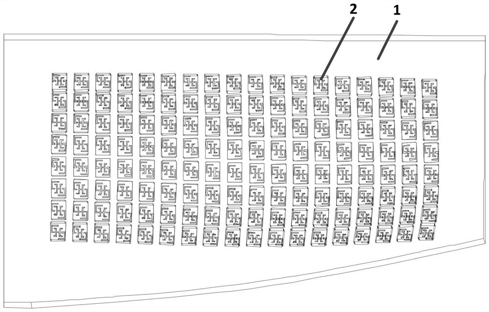
[0031] The ultra-low profile slot array antenna of the present invention includes a complex carrier 1 and an oblique diagonal slot antenna unit 2 , and the oblique diagonal slot antenna unit 2 is arranged on the complex carrier 1 .

[0032] The surface of the complex carrier 1 is an arbitrary curved surface, and the curved surface generally has a two-dimensional curvature. Since the diagonal slot antenna unit 2 needs to sink into the complex carrier 1, the surface of the complex carrier 1 is divided into a number of curved monomers with similar shapes, and each curved monomer is delineated backward The extension provides space for the slot antenna. The material of the complex carrier 1 is generally set to be metal.

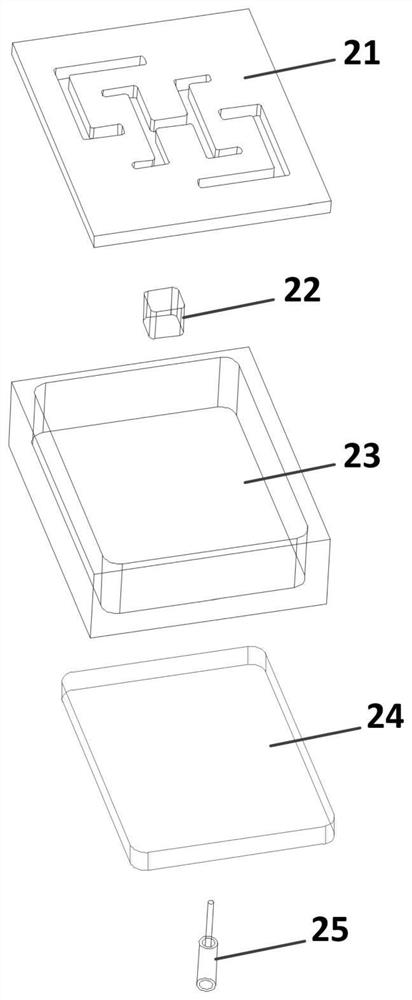
[0033] The diagonal slot antenna unit 2 includes a slot plate 21 , a resonant cavity 23 , an impedance matching block 22 , a resonant cavity back plate 24 and a feeding structure 25 ; the slot plate 21 is a part of the complex carrier 1 , It is located at the to...

Embodiment 2

[0051] like figure 1 shown, figure 1 This is a structural view of the ultra-low profile slot array antenna; in this embodiment, the ultra-low profile slot array antenna of the present invention is composed of 144 diagonal slot antenna units 2, operating at 4.5-4.7 GHz , the diagonal slot antenna units 2 are arranged in a rectangular grid, and Cosmol is used for grid division. The complex carrier 1 is intercepted from a certain aircraft body, and the curved surface shape of the complex carrier 1 is determined according to the aerodynamic performance. Design, which cannot be characterized by parameters, the antenna is modeled according to the above method.

[0052] like figure 2 shown, figure 2 is a structural view of the diagonal slot antenna unit; the diagonal diagonal slot antenna unit 2 includes the slot plate 21 , the impedance matching block 22 , the resonant cavity 23 , and the back of the resonant cavity. The plate 24 and the feeding structure 25, the outer dimensi...


PUM


Abstract

The invention discloses an ultra-low profile slot array antenna, comprising a complex carrier and an oblique diagonal slot antenna unit, wherein the oblique diagonal slot antenna unit is arranged on the complex carrier; the surface of the complex carrier is a curved surface; the oblique diagonal slot The antenna unit includes a slotted plate, a resonant cavity, an impedance matching block, a resonant cavity backplane and a feeding structure; the slotted plate is located at the top of the diagonally diagonal slotted antenna unit, and the upper surface of the slotted plate is the surface of the complex carrier. With the curved surface set, the slot plate is provided with a slot, and the lower surface of the slot plate is a plane; the resonant cavity is located directly under the slot plate; the impedance matching block is located in the resonant cavity and below the slot plate, and the impedance matching block is close to the slot. The back plate of the resonant cavity is located at the bottom of the resonant cavity; the invention realizes the zero section height of the forward antenna of the carrier, minimizes the influence of the array antenna on the aerodynamics and other properties of the carrier, and greatly improves the dynamic performance of platforms such as aircraft and stealth performance.

Description

technical field [0001] The invention relates to the technical field of array antennas, in particular to an ultra-low profile slot array antenna and a manufacturing method. Background technique [0002] In recent years, the development of airborne radar, satellite radar and missile-borne radar has become more and more mature. While paying attention to radar performance, the industry has begun to study the impact of array antennas on platforms. On the carrier platform, in addition to the high performance requirements of the antenna itself, the size of the antenna should also be limited. The quality of the antenna should be as light as possible, and the volume should be as small as possible, and scholars hope to reduce the impact of the antenna on the platform. to a minimum, so low-profile antennas are getting more and more attention. The low-profile antenna is based on the traditional antenna theory by adopting new ideas to achieve low-profile, these new ideas include new mat...

Claims


Application Information

Patent Timeline
Patent Type & Authority Patents(China)
IPC IPC(8): H01Q13/10H01Q1/50H01Q21/00G06F30/20
CPCH01Q13/10H01Q1/50H01Q21/00G06F30/20
Inventor 朱庆超方佳官伟金谋平张小林陶蕾刘颂阳
Owner CHINA ELECTRONIC TECH GRP CORP NO 38 RES INST
Why Eureka
Try Eureka